
How Does A Dynamo Work
Andrew grew up on a dairy farm and completed his first tractor engine rebuild around 50 years ago. With a degree in engineering Andrew, now retired, has time to pursue his interest in tractor restoration. Currently restoring IH tractors ’61 B275, ’67 B434 - Andrew has contributed to the International B Series Tractors Group and a number of instructional files to the International Harvester Club of Great Britain.
The following is a simplified description of how a dynamo produces electricity. It is only intended to provide the level of detail required to understand what the key parts do and why.
Terminology
Some people may be uncertain of the meaning of various terms used, so:
- Volts – the unit of “electrical pressure”analogous to water pressure.
- Amps – the unit of “electrical flow” analogous to water flow.
- Power = volts x amps and is measured in watts (1,000 watts = 1kW, 746 watts = 1 horse power.) Power is always power. It doesn’t matter if it is measured in watts, horse power, British Thermal Units per hour (BTUs for a boiler) as each has a fixed relationship to the others.
- Switch open – unlike opening a tap to allow water to flow, an open switch STOPS electrical flow. This is equivalent to switching something OFF.
- Switch closed – opposite to switch open. Allows electricity to flow, equivalent to switching something ON.
Dynamos produce power measured as a combination of voltage and current (watts.) When charging a battery the dynamo voltage must be above that of the battery for a current to flow, just as water will only flow from a higher pressure (which could just be height) to a lower. In the following description sometimes current is described because it is flowing through a wire and is the significant factor while at other times voltage is used because that is what “pushes” the electricity through the wire and is of primary relevance.
First Principles
Dynamos convert external power to electrical power. "There’s no such thing as a free lunch” – to get power out there first has to be power in.Electrical generators (magnetos, dynamos and alternators) and motors (DC and AC) are all based on electromagnetism. Magnetos are not covered in the following description but are based on permanent magnets to generate the magnetic field rather than the electromagnet in a dynamo.
“When a wire moves through a magnetic field it generates a current proportional to the strength of the magnetic field and the speed of movement through that field”
This one statement, possibly difficult to understand at first, is the basis of all rotating electrical generators – the rest is engineering to make and control the magnetic field, make the wires move through it and get the electricity generated to the outside world.
A Simple Dynamo
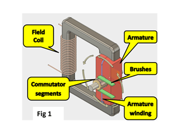
This is a simplified representation of a dynamo. The field coil, when electric current flows through it, makes the outer iron frame into an electro-magnet. The iron armature completes the magnetic circuit, just like putting a nail across the end of a horseshoe magnet. The more current flowing in the field coil, the stronger the magnet until a maximum, dependent on the metal inside the coil, is reached.
The armature winding is a loop (one or more turns) of insulated wire joining the two copper commutator segments together. When the armature spins through the magnetic field it generates a current in the winding – this current then goes via the commutator segments, through the brushes and out of the dynamo.
A Real Dynamo
The armature could be almost any shape – Fig 1 is quite short along the rotational axis but the types of dynamo in cars and tractors it tends to be long relative to its diameter as shown in Fig 2. A single winding only generates maximum power when it is moving at right angles to the magnetic field – the position shown in Fig 1.
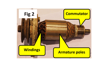
To get round this problem, a real dynamo armature as shown in Fig 2 has many windings arranged in a cylinder, each winding having its own pair of commutator segments making up the commutator. The armature poles in this picture is equivalent to the armature in the simple diagram and act to focus the magnetic field for each coil. The larger terminal (sometimes marked 'D') is the main power out connection and internally is connected to one of the two commutator brushes. The second commutator brush is connected to the dynamo case.
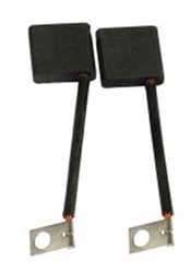
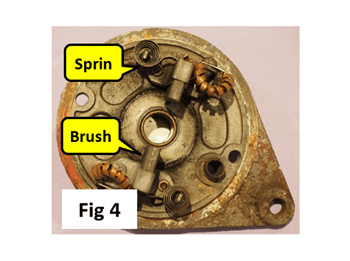
This an example of a pair of new brushes. Fig 4 shows the end plate of a Lucas dynamo. The dirt is carbon dust from brush wear in use. The spiral springs push the brushes against the commutator and their electrical connecting wire is screwed to the metal casting (ground side of dynamo) or to the 'D' terminal visible from the outside.
The end of the dynamo has two terminals. The smaller of the two is the field winding (sometimes marked ‘F’) with a standard ¼” spade connection. The other end of the field coil internally connected to the dynamo case.The larger terminal (sometimes marked ‘D’) is the main power out connection and internally is connected to one of the two commutator brushes. The second commutator brush is connected to the dynamo case.
Putting it All Together
If you have followed the explanation so far, you have probably worked out that there are two things that affect the maximum power any given dynamo can generate
- How fast it is rotating (output is proportional to speed of cutting the magnetic field) and this will depend on engine speed.
- The strength of the magnetic field and this depends on how much current is flowing in the field coil.
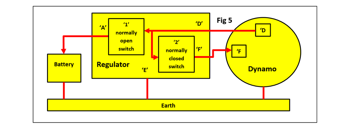
To stop a battery being over charged the dynamo output needs to be regulated. This is done by, not surprisingly, the regulator (sometimes called a controller or control box) which changes the field coil current as needed. This diagram is a very simplified explanation of a complex electro-mechanical unit. The dynamo earth connection is via its case, mount and vehicle chassis.
When the dynamo is stationary or first starts to turn, switch ‘1’ is open isolating the battery from the dynamo and switch ‘2’ is closed to couple the dynamo output directly to the field coil. The dynamo’s field coil iron core has a small amount of residual magnetism that allows a small current to be generated and fed, via switch’2’, to the field winding which increases the output still further and so on. When the dynamo is producing a high enough voltage switch ‘1’ closes and battery charging starts. Eventually the dynamo output needs to be reduced because the output current and/or voltage is too high and so switch ‘2’ opens to reduce the field current to compensate. This explanation isn’t 100% correct but is close enough to explain what happens – a full explanation is part of a degree in Electrical Engineering!
To understand how to check if your dynamo is working, read the next part of this series: "Testing Dynamo & Regulator"
ARTICLE CONTRIBUTED BY ANDREW CHAPMAN
© ANDREW CHAPMAN & ANGLO AGRIPARTS LTD


Licence Terms
You are free to: Share, copy & redistribute the material in original format for any purpose as long as you follow the license terms below:
- Attribution – you must give appropriate credit and provide a link to the original article in a reasonable and visible manner
- You may not in any way suggest that the licensor endorses you or your use.
- No Derivatives – The material must be distributed in full, including disclaimer, you may not distribute or share modified material.
- No additional restrictions – You may not apply legal terms that legally restrict others from doing anything the licence permits.
- No warranties are given. The license may not give you all of the permissions necessary for your intended use. For example other rights such as publicity, privacy, or moral rights may limit how you use the material.
Disclaimer


