International Harvester 434 Major Works Part 4 - Strip, Clean & Initial Inspection

International Harvester 434 Major Works Part 4 – Strip, Clean & Initial Inspection
Following on from the previous article on the overhaul of the cylinder head, this article continues with the stripping, cleaning and initial inspection of the various components fitted to the engine block.
The engine here is from an International Harvester 434. This is a BD154 engine as fitted to several tractors (B414, 434, 444, etc.), and almost identical to the BD144 engines (used in B250, B275, 276, etc.). It differs slightly from the early B250 which had an inline injector pump and a different timing gear.
The general processes however are very similar to most makes of engines and the information is therefore likely to be of more general interest.
Working on the inside of an old diesel engine is usually the dirtiest task in tractor restoration. The combination of oil, carbon and diesel coats everything in a black film that sticks to everything and is not much easier to get of skin than paint, so it tends to be a time for old clothes and protective gloves. This article is being written during Covid-19 lockdown, so unfortunately the gloves are in very short supply!
Because the filth from inside an old engine will get onto everything including self, clothes, tools and almost every surface, it is helpful to break the task down into three separate major tasks – strip, clean and inspect.
While an engine can be rebuilt without the use of an engine stand, a stand makes life much easier and is assumed below.
Strip
Before starting it is a good idea to have a collection of cardboard boxes and plastic bags (e.g. sandwich bags) plus an indelible marker pen. A paint pen can also sometimes be useful for marking items.
As the components attached to the block are removed they can be put into separate cardboard boxes (useful to absorb the mess and provide protection) and/or labelled plastic bags. Don’t put too much in any bag – when rebuilding some time later is very easy to forget which bolt goes where. Put the bags into one or more cardboard boxes as a bag with a small component can easily get misplaced. During handling, sandwich bags that have the white area for writing on tend to keep their labels visible much longer than the completely clear ones.
It is assumed that the cylinder head has already been removed as described in the previous article.
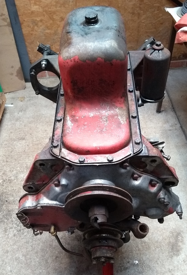
With the engine the normal way up, remove the oil filter and mount, the lift pump and oil pressure switch (or 90 degree coupler to gauge on earlier engines) and water pump.
With the engine inverted, remove the sump.
Remove the crankshaft pulley – a long bar between the two dowels on the other end of the crankshaft can be used to lock the crankshaft to undo the nut. There is a woodruff key in the crankshaft that should be removed and saved with the pulley and nut. Sometimes these are quite tight – I use a piece of brass to avoid damage when knocking the key out.
Remove the front plate from the timing cover, taking note of where the wiring loom clips are fitted. If you need to change the injection pump with the engine in place, this cover allows the timing gear to be removed (and re-timed later) before the pump is unbolted.
The timing cover can now be unbolted. The hydraulic pump is held in place by four of the bolts that also hold the timing cover on. The pump may come free (watch it doesn’t drop) but often it is a very tight fit/held in place by the gasket and stays in place. With the timing cover off it is possible to measure the gear backlash. This is however covered in a later article as with a filthy engine it is almost impossible to get meaningful photographs as everything is black on black.
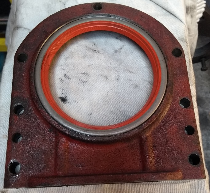
Similarly, the rear oil seal retainer can be unbolted.
Depending on the engine stand being used, there may be a clearance problem getting the bolts out as the gap between the rear of the engine block and the stand may not allow all the bolts to fully unscrew.
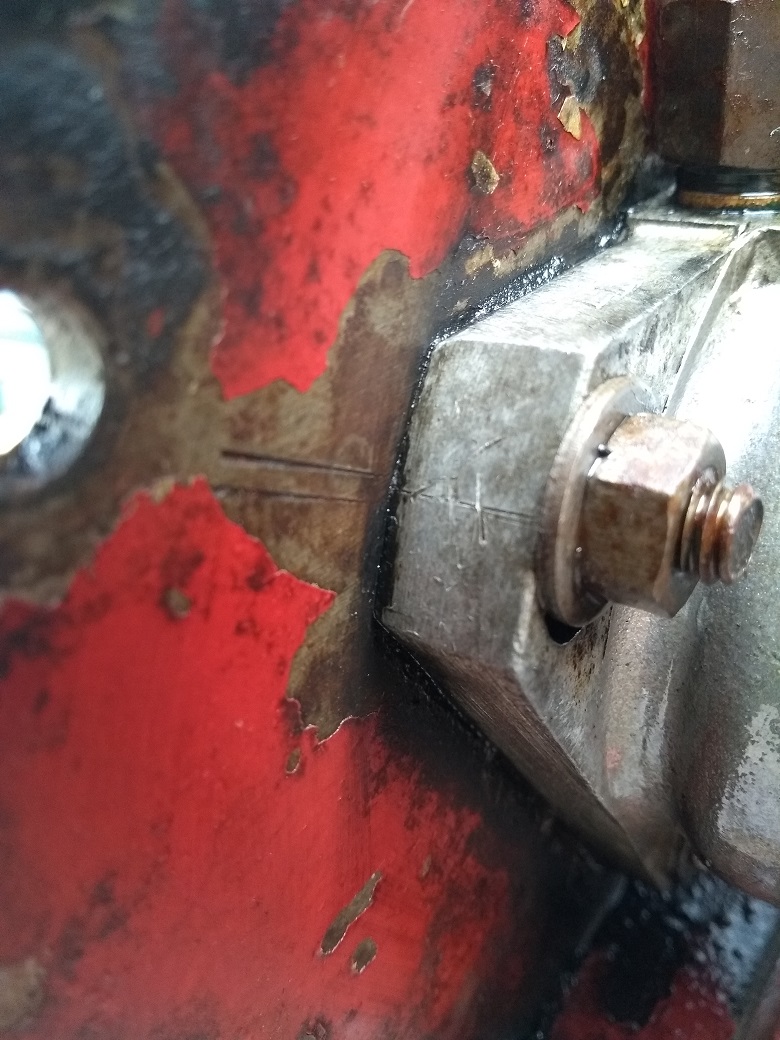
Before the injection pump is removed it is important to note its current timing settings. The pump is held in place by three studs and can be rotated slightly to adjust the timing.
This picture shows two lines on the engine front plate with the pump’s timing mark line mid-way between the two. Earlier engines may not have such marks so, if necessary, put a centre punch mark at the junction of the two (so part of the hole is in the pump and part in the plate).
The timing gear is held in place by three bolts and an alignment dowel. With the gear removed, the pump can be unbolted and removed.
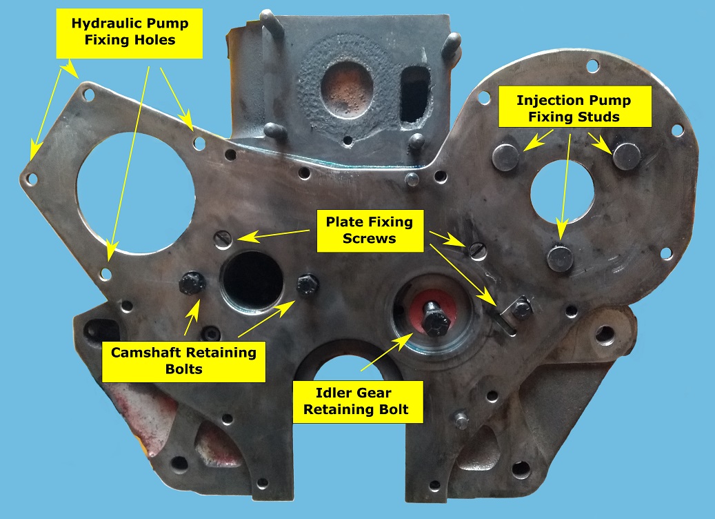
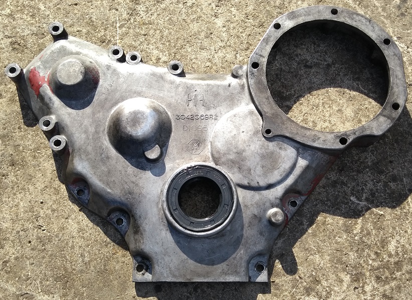
This picture shows the engine front plate after cleaning, to get a better picture of where the various parts fit. Much of this is hidden behind the timing gears
- The hydraulic pumps fits in the large hole top left.
- The injector pump fits in the smaller hole top right, bolted on the studs shown.
- The idler gear runs on, and is retained by, a flanged boss which also provides its lubrication. The boss is in turn retained by a single bolt.
- The camshaft is retained by two bolts through its thrust plate. These two bolts are accessed through holes in the camshaft gear. The original gears have 3 holes and so needs to be rotated between accesses to each bolt. Some replacement gears have only two holes. Only remove the camshaft with the engine inverted to stop the cam followers falling out.
- The engine front plate is located on two dowels (which also locate the timing cover) and retained by 2 slotted head countersunk screws and a single bolt with locking tab. On a dirty engine, the two slotted head screws may not be too obvious.
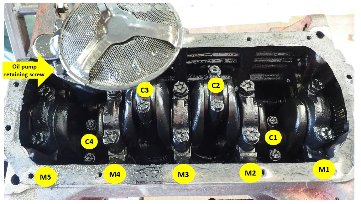
Single screw (shown by the arrow in the picture) is all that holds the oil pump in place.
The con-rods (C1-C4) are held in place by two bolts each. If not numbered already, it is a good idea to number the caps where the above labels are positioned in case you wish to re-use the pistons. Early engines have the bolts wired but later engines have dispensed with this feature.
With the big-end caps removed, the pistons should just push out through the tops of the liners. They will only go out through the top of the block.
A worn bore will have a ridge (possibly with carbon build-up too) above the limit of the top ring’s movement and this can sometimes make the pistons more difficult to remove. A length of wood acting on the underside of the piston and a GENTLE tap with a hammer should free them.
Keep the cap with its matching con-rod, and there is a right and wrong way round – three of the caps in my engine were the wrong way round. This will be explained in more detail when the engine is re-assembled. Some engines have the con rods and matching caps numbered.
The main bearing caps (numbered M1-M5) are also held in place by a pair of bolts. These caps are often numbered 1-5 and under the gasket is also often a matching number. If the caps aren’t numbered, mark them (e.g. with 1 to 5 centre punch dots or ink pen) as they MUST go back in their original place. Also the caps must go back the correct way round – there is a flat on the side that matches the oil pump and camshaft side of the engine as can be seen in the photograph. These caps are very closely machined and sometimes need a little persuasion to come out – use the unscrewed bolts in the holes to rock the cap from side to side and they should work their way out.
The crankshaft can now be removed along with its timing gear.
With the pistons and crankshaft out of the way it is a good time to assess the pistons, rings and bores. If the bores are scored, pitted or showing much of a ridge at the top, then it’s probably time to replace the liners and pistons. Check the pistons for stuck or bent rings and scoring. With the ready availability and relatively low cost of new liners, pistons and rings if there is any doubt it makes sense to renew. If necessary, pistons, rings and liners are available individually.
On this engine one of the oil control rings was badly bent and stuck in its groove. This could only have happened when the piston was installed (brute force rather than correctly compressing the ring) and there was abnormal wear to both the bore and side of the piston.
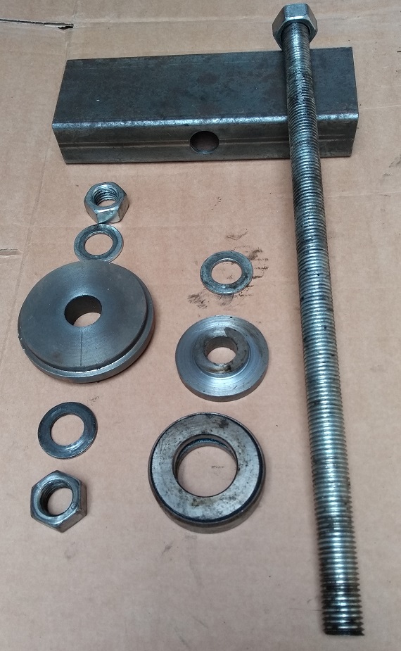
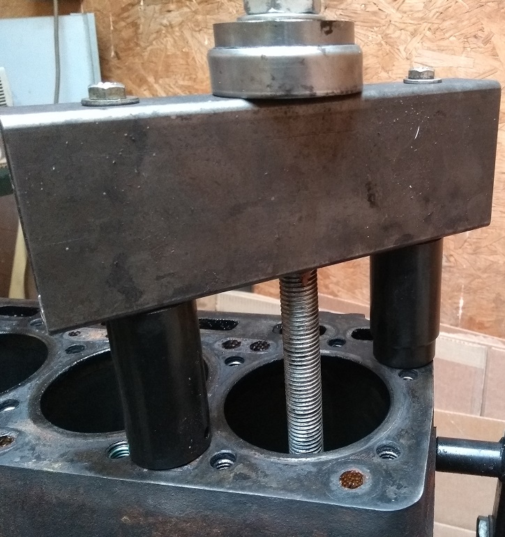
Assuming the liners need changing, some form of puller will be needed. There are several different designs but this is the one that I made from what I had around. I helped my father in the early 1960’s when we had two B414s that developed porous liners at about 18 months old… and we used carved oak blocks and threaded rod. Liners that have been in for a while tend to be more difficult to remove due to rust and scale build- up so this puller is somewhat stronger.
A length of 24mm threaded rod passes through a spacer and thrust race (spare from a front steering knuckle) and through a length of box section tube – the thrust race reduced the turning friction losses.
The large disk has an outside diameter that is slightly less than the liner diameter where it passes through the O-ring seal. The disk also has a reduced diameter section to locate closely with the bore - my disk has different reduced sections on each side to fit the different bores of the BD144 and BD154.
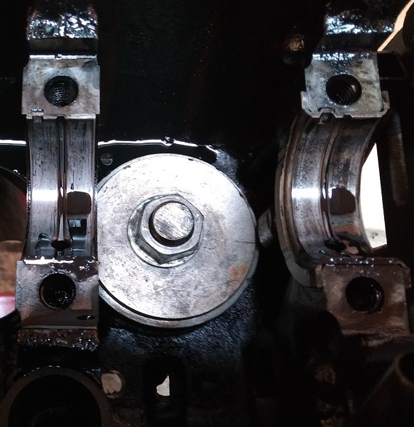
Unfortunately these engines will not allow this disk to pass between the main bearings without tilting, so I fasten the bottom nut with it held in place. It is possible to cut two flats to allow the disk to pass between the main bearings but, as I’ve had a liner shatter in the past, I prefer to maximise contact area.
I’ve a set of long impact sockets that I use as spacers between the box tube and the block. Take care not to damage the top of the block (I put the sockets with their square drive end against the block) and wind the liners out. Getting the initial movement can take some effort so you may need a long socket bar or a length of tube on a spanner… but after the first millimetre, they tend to come out relatively easily.
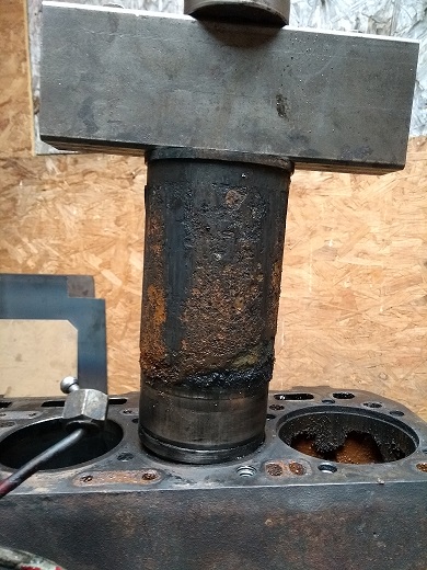
Once out, there’s probably a lot of scale to clear, typically worse around the back of #4 liner as its furthest away from the water pump.
This liner isn’t as bad as some I’ve seen. If the engine had been run without antifreeze then the scale could have been much deeper.
The dividing line between the water and oil is very obvious at the bottom of the liner.
Remove the liner sealing O-rings – don’t be tempted to re-use old ones as they are all that’s keeping the water out of the sump.
On this engine the old O-rings clearly hadn’t been changed when the liners were last replaced. One was almost out of its groove – amazing that it hadn’t leaked.
The O-ring groove needs to be carefully cleaned to ensure a good seal when the new O-ring is fitted. I find that a suitably sized Allen key (one that will just fit) works well to scrape the rubbish from the groove.
The camshaft and gear are removed together. There are two retaining bolts accessible through the holes in the gear. With the bolts removed and the engine inverted, the camshaft can be withdrawn.
Assuming the liners have been removed, the cam followers can be withdrawn relatively easily using a magnetic pickup tool. Take care to record which location each follower comes from so they may be replaced later in their original place.
Clean
Aim for “clean enough to eat your dinner off”. I tend to use engine degreaser initially and finish with spray brake cleaner – it is much nicer to work with clean parts for all the following stages and minor contamination can still ruin all the hard work of rebuilding an engine.
Once cleaned, don’t leave items like the crankshaft and camshaft unprotected for long. I usually give them a light spray with something like WD40 and wrap them in cling film (preferably the stronger industrial wrap type.)
The main engine block tends to be the most difficult to clean but don’t skimp it. I start with engine degreaser, pressure washer and repeat till it looks good then dry everything with an airline. After I followed-on clean with brake cleaner and a light spray with WD40 to stop things rusting.
An important area to clean is the oil galleries. There are several screw-in blanking plugs that need to be removed to gain full access both on the side and end of the block. On this engine I was unable to remove the one on the end of the block – after breaking a couple of Allen keys and a socket I ended up washing through with diesel and airline.
Initial Inspection
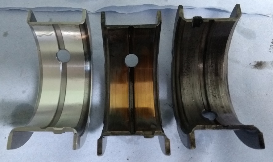
This picture shows three main bearing shells – from left to right these are new, bottom (from in the removable cap) and top. The top shell, while discoloured and with mild damage, is quite different from the bottom shell which has lost its entire bearing surface and just has the backing showing.
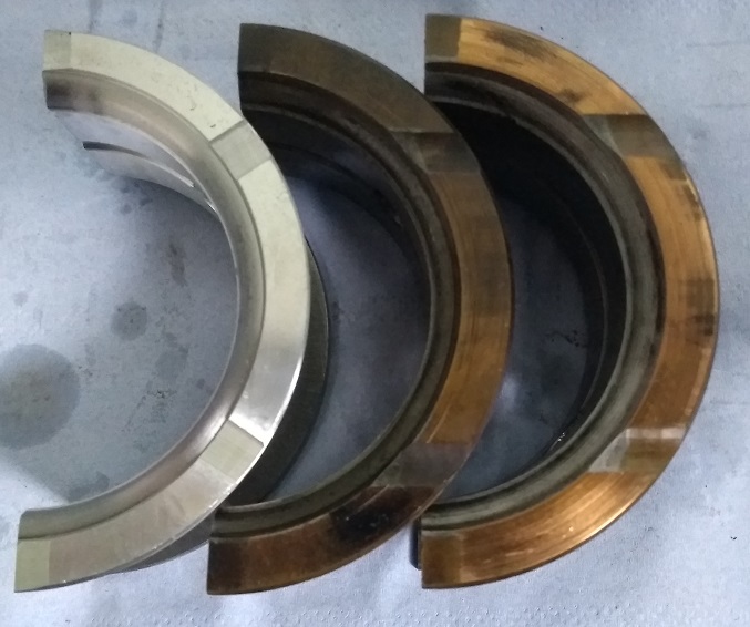
This picture shows the same three shells from the side. These are all from bearing #5 which is just by the flywheel and includes the thrust faces.
The two old shells actually show similar wear with the side nearest the flywheel (the face on the right shell) being the greatest. When the clutch is depressed, this is the face that takes the load.
The other face has lost its surface but isn’t too bad.
The big end shells were is a similar state so both sets clearly needed replacing.
The following articles will cover inspecting the timing gears, crankshaft, camshaft, small-end bushes plus oil and hydraulic pumps.
ARTICLE CONTRIBUTED BY ANDREW CHAPMAN
© ANDREW CHAPMAN & ANGLO AGRIPARTS LTD


Licence Terms
You are free to: Share, copy & redistribute the material in original format for any purpose as long as you follow the license terms below:
- Attribution – you must give appropriate credit and provide a link to the original article in a reasonable and visible manner
- You may not in any way suggest that the licensor endorses you or your use.
- No Derivatives – The material must be distributed in full, including disclaimer, you may not distribute or share modified material.
- No additional restrictions – You may not apply legal terms that legally restrict others from doing anything the licence permits.
- No warranties are given. The license may not give you all of the permissions necessary for your intended use. For example other rights such as publicity, privacy, or moral rights may limit how you use the material.
Disclaimer

Related Articles

Ferguson TED20 - Cleaning the Engine Tractor Video Tutorial
In this video Gordon from Waterhouse Forde cleans the engine on his Ferguson TED20 tractor.

International Harvester 434 Major Works Part 1 – Initial Strip-down
Contributor Andrew Chapman undertakes a major overhaul of his International Harvester 434. Part 1 is discusses the initial strip down of the tractor in preparation of the work.

International Harvester 434 Major Works Part 2 - Cylinder Head Overhaul
Contributor Andrew Chapman undertakes a major overhaul of his International Harvester 434. In part 2 he covers the cylinder head and valve overhaul.
-200x200.png "International Harvester 434 Major Works Part 3 - The Oil Filter That Didn't")
International Harvester 434 Major Works Part 3 - The Oil Filter That Didn't
An oil filter is meant to filter oil and this engine didn’t filter oil at all. Read Andrew Chapman's article as he investigates the issue with his BD154 engine on an International Harvester 434.

International Harvester 434 Major Works Part 5 - Timing Gears
The latest in Andrew's series of articles recording the major overhaul of his International Harvester 434 tractor. In this instalment Andrew focuses on timing gears.