International Harvester 434 Major Works Part 9 – Crankshaft

International Harvester 434 Major Works Part 9 – Crankshaft
This article describes the installation of the crankshaft, main and big-end shells in an International Harvester 434. This is the same procedure for all the BD154 engines (tractors B414, 434, 444, etc.) and BD144 engines (B250, B275, 276, etc.) It is similar enough to most makes of engines so is likely to be of more general interest.
This engine had a badly worn crankshaft. All bearing surfaces were badly scored and the area where the rear seal runs had a deep groove. It would therefore need either a regrind plus wear ring for the seal surface or a replacement crankshaft.
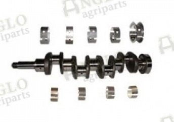
Anglo’s crankshaft kit (A50281) was much cheaper than a regrind. This kit includes the crankshaft, main and big-end bearings, front and rear oil seals but doesn’t include the flywheel locating dowels, woodruff keys or crankshaft gear. The lack of dowels was an issue as these had to be made (the old ones are impossible to remove). The old woodruff keys could be reused and I had to find a replacement gear as the old one was badly worn.
I’ve had bad experiences with the local engine rebuilders, so a replacement was the solution chosen. Unfortunately, and for reasons explained later, this didn’t go as smoothly as it should… but there were some useful lessons learned as a consequence.
Making Replacement Dowels
Two 7/16” diameter dowels are used in the end of the crankshaft to accurately align the flywheel. There is a register recess in the flywheel but, as the engines were designed to use dowel as well, that is how I wished to rebuild it. Dowels ensure that the thread on the flywheel retaining bolts doesn’t rub on the side of the holes and the retaining torque should be more consistent.
Unfortunately I couldn’t find a source for the correct sized dowels, at least without ordering a very large quantity. I eventually found 7/16” silver steel via eBay and used that. Later however I found that a supplier I’ve used for years for taps and dies, Tracy Tools, could also supply high speed steel drill rod in standard drill diameters and lengths for about £5 to £6. Silver steel is only available in limited sizes so, if you don’t have a lathe to turn some down to a specific size, the drill rod would make an easier solution for almost any size dowel – just cut to length and grind a chamfer on each end. They can also produce items to custom sizes at reasonable prices.
Having made the dowels, when I came to fit them I found a major issue with the crankshaft – the dowel holes hadn’t been machined to size! I discussed the problem with Anglo who checked and found that the rest of the batch had the same problem. The quality of aftermarket parts sometimes leaves something to be desired, but if we as customers don’t raise the issues our suppliers will miss the opportunity to push for better parts. I’ve found Anglo to care about this type of problem but one other “big name” supplier I know who takes the general attitude of “just send it back”… and then are happy to send it to someone else!
There are a very limited number of manufacturers of these crankshafts so the problem was unlikely to be limited to just Anglo. As this work was carried out just after Brexit and during the Covid lockdown, finding another crankshaft soon looked problematic… and I could end up getting replacements from other suppliers with exactly the same problem. I therefore had three choices:
- Regrind the old crankshaft - wasn’t happy with that as explained earlier.
- Rebuild without the dowels - uncomfortable with that as it may have built in a problem for the future.
- Rework the Anglo crankshaft – as the crankshaft would otherwise have been scrap, this is the approach taken and subsequently successfully completed.
Crankshaft Rework
In a big professional workshop, re-machining the dowel holes shouldn’t be too much of a problem, but how to do it in a home workshop?
As there is a reference recess in the flywheel which is a tight fit on the crankshaft, the flywheel dowel holes potentially provide a reference for re-machining the crankshaft. One concern I had was that the end of the crankshaft that I wished to machine may have been hardened, but this subsequently proved not to be the case.
I purchased a 7/16” D-bit from Tracy Tools, bolted the crankshaft to the flywheel and supported everything in my workmate with the flywheel flat on its surface. I would have preferred to use my magnetic drill to ensure that I was perpendicular when drilling, but unfortunately I could find no way to clamp it.
A trial with my had-held battery drill confirmed that the crankshaft could be drilled… but then found that the existing dowel pilot holes weren’t even on the centreline! Because the existing undersize hole was off the centreline, drilling was producing a hole with part of the original hole outside the dowel so it wouldn’t locate correctly.
The flywheel is held in place by 4 bolts which appear to be in a square. Rotating the flywheel 90 degrees and trying the bolts actually showed that there was a slight difference – the bolts would fit but were tight against the sides of the holes.
D-bits aren’t the best tools to remove a large amount of material so I made a couple of drilling guides from the spare silver steel that I’d bought for the dowels and hardened them. I was the able to drill out the bulk of the material before finishing up with the D-bit.
Dowels into a blind hole can cause problems as there’s nowhere for the air being compressed to escape. A very small flat on the side of the dowel resolves the problem. The dowels were then tapped through the flywheel and into the crankshaft leaving their top surface flush with the flywheel. The flywheel was then removed.
The end result was a successful rework… and some useful techniques learned.
Fitting the Crankshaft
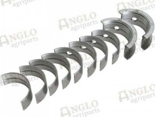
After the diversion with the rework, the following tasks were easy and straightforward. The set of main bearing shells contain three different types:
- Ones with side flange and hole – these are identical top and bottom and provide the thrust faces which control crankshaft end float.
- Ones with hole – these allow lubrication from the oil pump and must be fitted into the block with the oil hole aligned.
- Ones without hole – these fit into the bearing caps.
Before fitting the bearings into the block, ensure that the surfaces are clean and the oilways clear.
The crankshaft timing gear can be fitted before or after the crankshaft is installed. If the gear is already on the crankshaft then the timing relative to the camshaft MUST be correctly set when the crankshaft is fitted, or the camshaft will need to be withdrawn enough to set the timing.
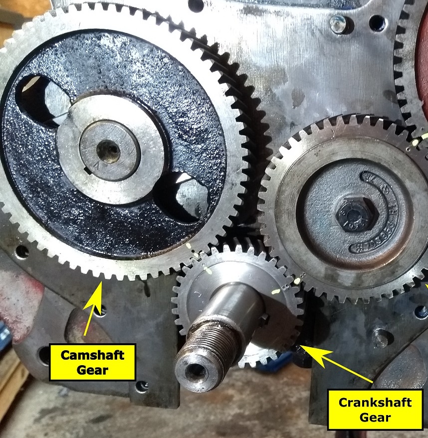
This photograph shows one of the new Anglo timing gears – the original IH ones have three holes. The camshaft gear has a single punched mark which must align with the single mark on the crankshaft gear. The double punched mark on the crankshaft gear will align with the equivalent double mark on the idler gear when it is subsequently fitted, but it is recommended that the idler gear isn’t fitted at this time as it will be easier to install and time with the injection pump.
Lubricate the bearing surfaces with engine oil and press into place. Sometimes a slight tap with a rubber hammer can help seat them but they shouldn’t require much force. Add additional oil to the oilways so when the engine is first run there will be plenty of oil in the critical first few revolutions. Two revolutions of the crankshaft correspond with one revolution of the camshaft, so the timing marks should come back into alignment.
Oil the crankshaft main bearing surfaces, position the crankshaft in the bearings and spin it to ensure it rotates freely.
Fit the remaining bearings into their caps, oil and loosely tap the caps into place guided by their fixing bolts. Make sure that the caps are in the correct location as indicated by the number stamped onto them – the number should match the number on the block and be on the camshaft side of the engine.
Gradually tighten the main bearing bolts, regularly rotating the crankshaft to confirm it isn’t pinching. Finally torque the bolts to their correct settings which differ depending on the type of bolt fitted:
- White painted bearing caps 95/100 lb ft
- Bolts using lock wires 70/75 lb ft
- Other bolts 80/85 lb ft
Again confirm that the crankshaft turns freely.
The big-end shells can now be fitted in the same way as the main bearings, again using plenty of oil. The torque setting for these bolts is 40/45 lb ft.
Rotating the crankshaft now will require more effort but it should turn using a lever between the dowel pins and feel similar resistance across all 4 piston movements.
The next article in this serial will look at the oil pump and assessing its condition.
ARTICLE CONTRIBUTED BY ANDREW CHAPMAN
© ANDREW CHAPMAN & ANGLO AGRIPARTS LTD


Licence Terms
You are free to: Share, copy & redistribute the material in original format for any purpose as long as you follow the license terms below:
- Attribution – you must give appropriate credit and provide a link to the original article in a reasonable and visible manner
- You may not in any way suggest that the licensor endorses you or your use.
- No Derivatives – The material must be distributed in full, including disclaimer, you may not distribute or share modified material.
- No additional restrictions – You may not apply legal terms that legally restrict others from doing anything the licence permits.
- No warranties are given. The license may not give you all of the permissions necessary for your intended use. For example other rights such as publicity, privacy, or moral rights may limit how you use the material.
Disclaimer
-500x500.png "International Harvester 434 Major Works Part 9 – Crankshaft")
Related Articles

Tractor Crankshaft
What is a crankshaft?
What are crankshafts made of?
What parts does a crankshaft have?
Why do crankshafts fail?

Ferguson TED20 - Fitting the Crankshaft - Video Tutorial
Gordon and Oscar fit the crankshaft - fundamental in converting the up and down motion of the pistons to a rotational movement of the engines output shaft.

International Harvester 434 Major Works Part 6 - Camshaft
The camshaft and cam followers (tappets) are often ignored during an engine rebuild - in this article contributor Andrew explains how to check them, and how to change the gear or adjust the end float.