Cylinder Head Gasket Failure in Tractors

An International Harvester ’61 B275 required an engine rebuild after being left in a field for about 7 years. Water had got into the liners and two (non-adjacent) cylinders had very low compression but there was no obvious sign of a blown head gasket. However, when the head was removed there were signs of a leak from one cylinder.
A friend’s recently acquired ’64 B414 had an obvious head gasket problem - low compression on one cylinder and oil in the radiator header. When the head was removed, serious cylinder head damage was found due to running the engine for an extended period with a leaking gasket.
After looking at both gaskets, it raised the question of how common were these failures and what was the explanation?
Example Cylinder Head Gaskets
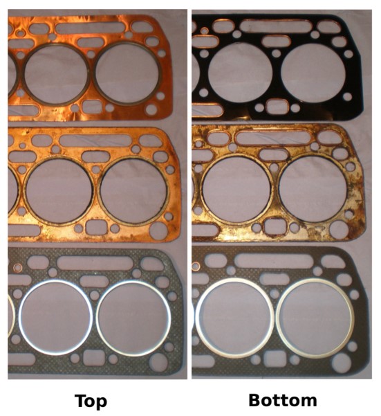
The two old gaskets plus two different types of replacement were all examined. Three head gaskets are shown in the following image. From top to bottom they are:
- New gasket, solid copper top face, steel rear face, damaged in transit by cylinder liners bouncing on it. Unlike the other two gaskets there was only a narrow raised steel lip, formed from the back steel sheet, as the liner seal.
- Used gaskets as fitted to both tractors, again with solid copper top face and rear steel face. One of these was fitted with rubber sealing washers in the water jacket circular holes – neither showed signs of leak in this area.
- New gasket (copper saving apparently) with steel core and gasket material for both top and bottom faces but steel reinforcing for the liner seals and copper seal for the rocker shaft oil feed.
There were no obvious reasons found to indicate that any of the three types had any design or manufacturing defects so suspicion has to fall on poor assembly.
Preliminary Inspection
Both tractors had exactly the same make and model of head gasket and while the B275 looked ok, the B414 (Fig 1) was a mess. Despite having the same gasket, the B414 had two rubber washers (visible at the top of the cylinder head) sealing holes for the water jacket but neither showed signs of leaks in this area.
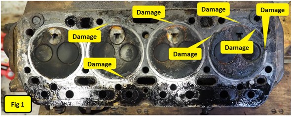
The first impression was the amount of oil on the top side of the gasket and cylinder head face. The lower side of the head gasket and top of the block were clean so the problem was between head and gasket. Closer inspection showed that all four pre-combustion chambers were cracked and that the gasket had been leaking in at least three places with leaks between cylinders, and cylinder to rocker shaft oil feed and cylinder to water jacket. Just some of the damage is highlighted in Fig 1
The underside of the head gasket around the rocker shaft oil feed hole, which is normally raised above the surrounding gasket (to give a higher pressure seal), was crushed flat with the surrounding gasket, unlike the same gasket from the B275. This possibly explained the oil leak… or the bolts may even have been over tightened in an attempt to stop an initial oil leak.
Fig 2 shows corrosion at the top above the pre-combustion chamber where combustion gasses have been leaking and water entering.
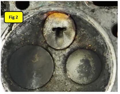
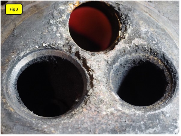
Fig 3 shows the worst part of the cylinder head where there had been the leak. The head was badly eroded around both valves (especially intake) and around the pre-combustion chamber.
The other three cylinders showed less severe damage but also gave the impression that water was passing via the open inlet valve on the faulty cylinder into the inlet manifold and then into the other cylinders.
This head had been removed with a torque wrench to see how close the bolts were to recommended torques. Approximately half of the bolts were around the correct 75 to 80 ft lbs but the remainder were all over the place – some loose and some over tight.
The head from the B275 however was generally OK but still showed signs of a leak between cylinders 2 and 3 near the rocker shaft oil feed-hole.
The liners on both tractors had obviously been replaced and not done many hours afterwards. The original honing marks were very clear on the B414 although the cylinder head hadn’t been reconditioned at the same time as all the valve guides were badly worn.
Head Bolts & Rocker Shaft
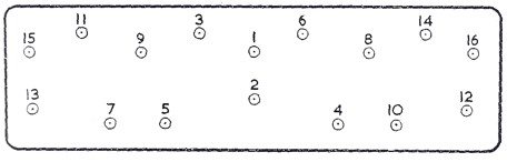
The cylinder head is held in place by 16 bolts, 15 shorter ones and a longer bolt that passes through the middle rocker shaft retaining bracket. From the workshop manual the tightening order is as in this diagram (front of engine to the left) with number 1 being the long bolt.
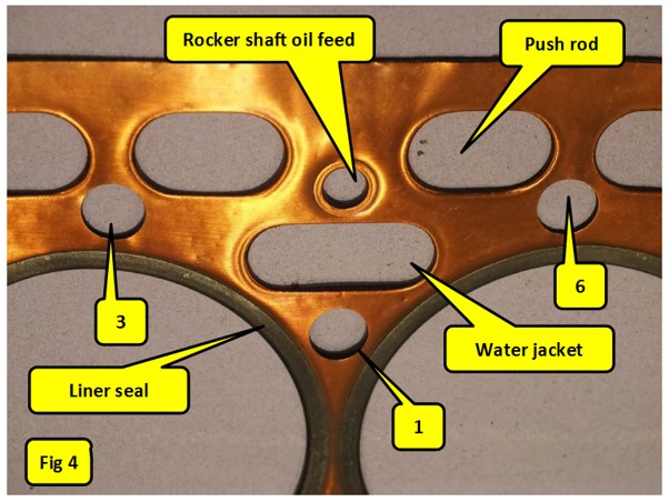
This photograph is of a new gasket that couldn’t be used due to damage in transit when it was packed with the new liners for the B275 but no consideration of what would happen when the liners bounced on it! It is however helpful in identifying where the problem areas are.
The top four oval holes at the top are for the push rods. The numbered holes correspond to the cylinder head bolt numbers in the previous diagram. The water jacket hole obviously is one of the paths that water flows between engine block and cylinder head. On this style of gasket (and there are several different designs in use) the top copper face is rolled over on the reverse side (like the rocker shaft oil feed on the top surface) to provide a raised lip to increase the pressure at the point of sealing.
The liners come in for special treatment in that they have an additional pressed steel reinforcing ring (it looks the same on both sides.) Correctly installed liners should have their top face between 1 and 5 thou higher than the engine block to ensure that there is greatest clamping force around this steel ring. This seal therefore relies on steel to steel (liners) and steel to cast iron (cylinder head) joints and is subject to the highest sealing pressures and temperatures anywhere in the engine excluding the valves in their seats. When rebuilding an engine the liners, being turned parts, only have fine machining marks tangentially to the bore (i.e. in circles round the bore) on the gasket mating face and so provide a very good sealing surface… which probably explains why there were no signs of leakage in this area on either tractor.
The cylinder head face however is another matter. Any pitting, radial surface scratches or other damage where the head gasket steel faces meet creates a weakness that could lead to failure so this is an area that should always get special attention when preparing the cylinder head. As the B414 didn’t get a cylinder head overall, possibly the gasket sealing face condition was also ignored or given minimal attention.
To ensure the best chance of a good seal, finish the cylinder head face with wet-and-dry paper lubricated with thin oil, diesel, white spirit or paraffin. End up with 240 or finer grit, backed with a flat plate or board. One is looking for a satin finish with NO defects where the still ring will fit.
The other hole so far not mentioned is the rocker shaft oil feed. This is sealed with a hollow copper rivet so again it will be subjected to higher clamping forces than the surrounding gasket as the rivet is raised above the gasket on both faces. This helps ensure that the oil pressure doesn’t cause this joint to fail.
Finally, head gaskets should be assembled dry (i.e. no jointing compound) but IH recommend smearing all faces with a light coating of engine oil. The oil is not there as a seal but helps the gasket move slightly as the bolts are torqued down.
So Why Did These Gaskets Fail?
There are three main ways that the gasket could fail:
- The mating surfaces weren’t clean or were damaged. This especially applies to the cylinder head as is being reused and may not have been cleaned as well as necessary.
- Jointing compound had been used. Compounds such as Hylomar are great for most sealing jobs but have a maximum operating temperature of 150 degrees C, far too low to stand up to combustion temperatures. Over time such compounds will degrade leading to a risk of failed seal.
- Incorrect head bolt torquing. This could include too tight, too slack, wrong order or not torqueing down after the engine has been run for a few hours.
Mention is sometimes made of cylinder heads warping. This is highly unlikely with 50 or 60 year old cast iron. Cast iron can warp when the hard surface skin is machined off - sometimes casting were left outside to “weather” for several months after initial machining to stabilise before final finishing, but don’t tend to change later.
Both of these engines showed no signs of jointing compound but, interestingly, the problem areas were around bolt number 1, the bolt that holds the central rocker shaft bracket.
These IH engines are unusual in that they have a split rocker shaft, something that catches the unaware when they take one off and everything falls apart on the floor, assisted by the various rocker shaft springs. It looks as if the original engineers were short of space to fit a central bolt to hold the rocker shaft as is common on most engines, doubling up on the use of a head bolt. There are however significant consequences of this design decision as you can’t get access to all the head bolts with the rocker shaft in place. One consequence is that the rocker shaft needs to be split in order to not need to disturb a head bolt to fit it.
The unusual sequence for assembling the head from the workshop manual is as follows:
- Apply a light coating of engine oil to the cylinder head mating faces (i.e. top of block and cylinder head face.)
- Screw in two guide studs to the block. These are described as 0.45” ground rod, tapped 7/16” UNC one end and a screwdriver slot at the other. I find the cylinder head heavy to accurately move on my own so suspend it from the engine crane and leveller, lower it to about ¼” above the block then slide the gasket into place and align with bolts dropped through the head before finally lowering it into place, not needing such studs. Some engines actually have two studs fitted and 13 short plus one long head bolt.
- Install the cylinder head
- Install the centre rocker shaft bracket with its long bolt
- Install the remaining head bolt, replacing the guide studs when appropriate
- Tighten down the bolts in the specified order and to the required torque. It may also help to tighten down in stages (e.g. 20, 40, 60 then the final 75 to 80 ft lbs.)
- Remove the rocker shaft bracket and bolt.
- Install the push rods.
- Reassemble the rocker shaft, refit and torque down the long bolt again.
One problem with this is that the critical number 1 bolt has to come out and potentially disturb the head gasket in the vitalarea. A way round this problem would be to amend the procedure slightly as follows:
7. Remove the two outer rocker shaft retaining studs.
8. Install the push rods.
9. Slacken off the rocker adjusters.
10. Reassemble rocker shaft, inserting retaining studs and bolting down.
This way the central bolt doesn’t need to be removed – more work but lower risk of a failure. This process could also be used to remove the rocker shaft without disturbing bolt 1 when re-torquing the head at a later date.
ARTICLE CONTRIBUTED BY ANDREW CHAPMAN
© ANDREW CHAPMAN & ANGLO AGRIPARTS LTD


Licence Terms
You are free to: Share, copy & redistribute the material in original format for any purpose as long as you follow the license terms below:
- Attribution – you must give appropriate credit and provide a link to the original article in a reasonable and visible manner
- You may not in any way suggest that the licensor endorses you or your use.
- No Derivatives – The material must be distributed in full, including disclaimer, you may not distribute or share modified material.
- No additional restrictions – You may not apply legal terms that legally restrict others from doing anything the licence permits.
- No warranties are given. The license may not give you all of the permissions necessary for you intended use. For example other rights such as publicity, privacy, or moral rights may limit how you use the material.
Disclaimer

Related Products


