International Harvester 434 Major Works Part 8

International Harvester 434 Major Works Part 8 –Pistons & Liners
This article describes the installation of a new set of liners and pistons in an International Harvester 434. This is the same procedure for all the BD154 engines (tractors B414, 434, 444, etc.) and BD144 engines (B250, B275, 276, etc.) It is similar enough to most makes of engines so is likely to be of more general interest.
It is assumed for this article that the earlier parts of this series have been read and the old liners removed – if not then read Part 4 for the description of the liner removal.
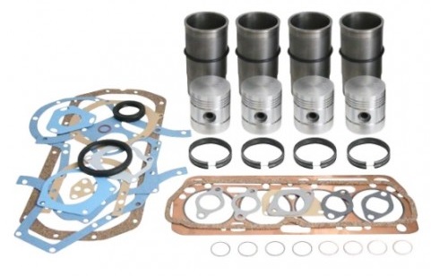
Anglo is very flexible in how they sell parts for this aspect of the rebuild. A comprehensive kit (engine overhaul kit A67337) includes pistons, rings, liners and O-rings, gaskets and crankshaft seals. Each of these parts is also available separately, although if some work is necessary then it normally makes sense to swap everything at the same time.
Installing the O-Rings
The O-rings are all that keeps the cooling water out of the sump so ALWAYS replace with new ones when changing liners. Part 4 describes the removal of the old O-rings and the important step of cleaning the groove that they fit in. Do not cut corners on cleaning this groove or all the effort in rebuilding the engine could be wasted. On this particular engine the O-rings hadn’t been changed when it had previously been rebuilt and one was badly damaged… it was surprising that it hadn’t leaked.
With a clean groove, lubricate the O-ring well with neat washing-up liquid and locate in the groove. This is normally quite easy, but check that the O-ring seems uniformly seated.
Installing the Liners
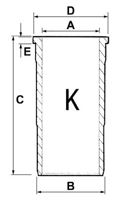
The liners are a snug push fit with the O-ring sealing on the smaller diameter (‘B’ in the drawing.)
The flange (‘E’ in the drawing) fits into a recess in the engine block but is intended to stand very slightly (1 to 5 thou) above the top of the block. This slight projection ensures that the cylinder head gasket is clamped most tightly around the top of the liner, so it is important that the recess is perfectly clean before inserting the liner or it may sit too proud and cause problems with the seal. I usually scrape the corners out with a Stanley knife blade and then clean the surface with brake cleaner.
Lubricate the outer surface of the liner along the reduced diameter (‘B’), not forgetting the chamfer at the bottom which guides the fit into the O-ring.
Press the liner in by hand, rotating gently a little to help align with the O-ring. The liner should normally press into the O-ring with hand pressure only. I normally use the disk that fits the liner for extraction to help pressing in at this stage although a flat piece of wood would work ok too. If you can’t get the liner to start into the O-ring then a GENTLE tap with a soft-faced hammer may be needed but, if it needs more force than that, something is wrong and needs rectifying or you’ll damage the seal.
Once the liner is sliding through the O-ring it should move smoothly but may need a tap with the soft faced hammer to finally seat the flange into the block.
NEVER HAMMER DIRECTLY ON THE LINER.
Finally, check the standoff of the liner above the block. I use a steel ruler standing on the top of the liner and a feeler gauge. If the liner is too high then either there is dirt in the recess or it isn’t tapped fully home. It is better to withdraw the liner again and fix the issue rather than cause head gasket problems later.
Fitting Piston to Con-rod
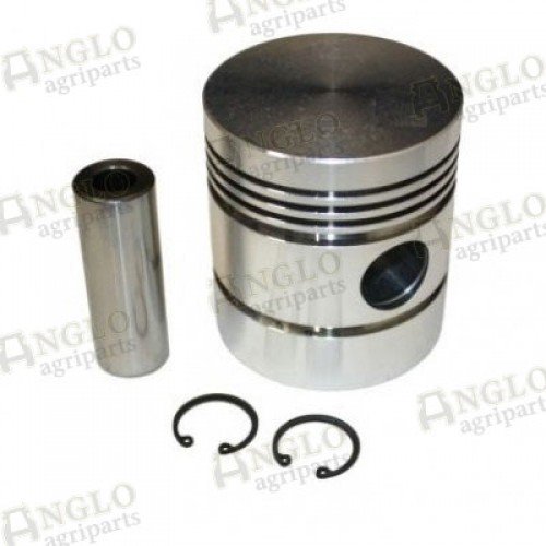
On some engines the piston must be fitted a particular way round on the con-rod. If you are rebuilding an engine with a piston with other than a simple flat surface like this one, check which way is correct.
The piston pin is a tight fit in the piston but should be a close sliding fit in the con-rod’s small end bush. Assembly is made easy by first fitting one circlip then putting the piston in hot water (hot tap temperature is usually ok) to expand it enough that the piston pin will slide in. Apply engine oil to both the small-end bush and the piston pin then assemble the piston onto the con-rod.
Fit the second circlip.
Fitting Piston Rings
It is much easier to fit the rings when the piston is on the con-rod as the assembly can be supported by the con-rod. I normally hold it in the wooden jaws of my workmate which then also provides a convenient surface to hold the rings and tools.
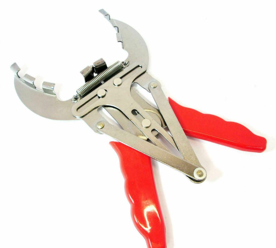
For years I fitted rings without special tools but one has to be careful not to break the rings or score the piston in the process.
Cheap ring expanders like this are readily available via eBay and well worth buying as they make fitting the rings much simpler.
As can be seen from the photograph of the piston, 5 rings are used – the bottom 2 are for oil control with 3 compression rings above.
Anglo provides rings individually packaged and identified. The top ring has a right and wrong way up so make sure to fit it correctly – if other rings have a correct orientation they should be marked on the packaging and the ring’s face. The oil control rings supplied were one-piece parts although I’ve also had multi-part rings in the past from other suppliers
Installing Pistons into Liners
The con-rods on these engines are numbered with their number being stamped into both the con-rod and bearing cap. Number 1 piston is at the front of the engine and, when inserted, the numbered side is on the same side of the engine as the camshaft.
Here is another case where for many years I managed to fit pistons into bores without tools, but it’s a fiddle. A low cost ring compressor (again via eBay) makes the task much easier.
The one I bought had a rather long spring (the blue/black part in the picture) so I cut some of it off with a cutting disk. The extra-long spring made it more difficult to get the correct squeezing on the rings and, as I didn’t envisage using it on much bigger pistons, there was no reason not to shorten it.
Before the piston is inserted the rings need to be aligned so their gaps are at about 180 degrees to their neighbours. This maximises the distance that gasses have to pass when they leak through the ring gaps. For convenience I usually line up the gaps with the piston pin, but this isn’t critical.
Apply engine oil liberally to the inside of the liner, the piston, rings and the inside of the ring compressor. Gently lower the piston into the liner until it is just resting on the lower ring.
Fit the ring compressor over the piston and tighten the ratchet while pushing the compressor firmly against the top of the liner. How tight is a little trial and error until one learns the correct tension but generally is as tight as possible while still allowing the piston to JUST slide.
Tap the piston gently (I normally use the wooden handle of a hammer.) This shouldn’t take a lot of force – if it doesn’t move then either the compressor is too tight (clamping on the piston) or too slack. If it is too slack and you try to force the piston the ring will either bend or break. One of the pistons removed from this engine had a badly bent oil control ring from when too much force had been used during installation. Generally, once the first ring enters the liner the others tend to follow ok but, if you meet resistance at subsequent rings the compressor may need tightening further.
Leave the piston flush with the top of the liner as this will make life easier when you come to fit the big-end shells later.
Aftermarket parts tend to be of variable quality. This engine rebuild kit however was super both in the quality of the parts and the care in packaging. From other suppliers in the past I’ve had damaged parts due to incorrect packaging – broken rings and twisted head gaskets.
The next article in this series will cover the fitting of the crankshaft and its bearings including connecting the con-rods.
ARTICLE CONTRIBUTED BY ANDREW CHAPMAN
© ANDREW CHAPMAN & ANGLO AGRIPARTS LTD


Licence Terms
You are free to: Share, copy & redistribute the material in original format for any purpose as long as you follow the license terms below:
- Attribution – you must give appropriate credit and provide a link to the original article in a reasonable and visible manner
- You may not in any way suggest that the licensor endorses you or your use.
- No Derivatives – The material must be distributed in full, including disclaimer, you may not distribute or share modified material.
- No additional restrictions – You may not apply legal terms that legally restrict others from doing anything the licence permits.
- No warranties are given. The license may not give you all of the permissions necessary for your intended use. For example other rights such as publicity, privacy, or moral rights may limit how you use the material.
Disclaimer

Related Articles

Ferguson TED20 - Removing Valve Stem Guides #2 & Dismantling Pistons Tractor Video
In this video Gordon from Waterhouse Forde removes valve stem guides of his Ferguson TED20 tractor and dismantles piston rings, gudgeon pins and the connecting rods.

Ferguson TED20 - Installing The Pistons - Video Tutorial
Progress is being made! - In their latest video Gordon & Oscar install the pistons - the beating heart of an engine. Combined with piston rings they perform the crucial task of creating an airtight seal between the combustion chamber and the crankcase. The pressure allows the piston to move up and down within the hollow cylinder of the engine block.

International Harvester 434 Major Works Part 7 - Small End Bush
The connecting rod small end bush is an often overlooked area when rebuilding an engine. In his latest article in the series, contributor Andrew looks at how to achieve close tolerance fits between parts on his International Harvester 434.