A Guide To Electrical Parts
Anglo Agriparts stock electrical parts for commercial, plant, agricultural, construction and marine application, we specialise in starter motors, alternators, voltage regulators, dynamos and other electrical items including instruments to monitor oil pressure, water temperature, oil pressure, tachometers etc.
Our range covers vintage, classic and modern day vehicles. We sell brand new and factory remanufactured units, our inventory is constantly being renewed, updated and expanded in range to meet our customer’s needs. Our specialist knowledge and first class customer service have resulted in us being a leading supplier to customers around the world. We offer next day delivery in the UK, with efficient low cost courier services to all the countries of the world using our courier partners.
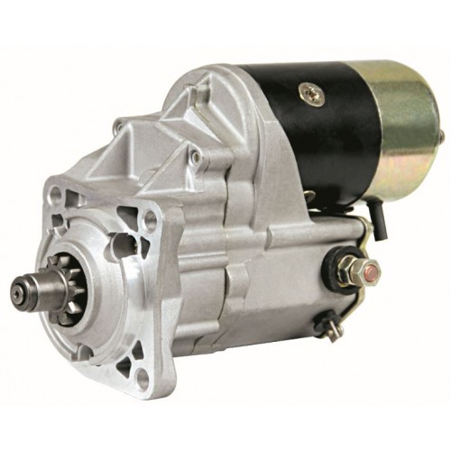
Starter Motors - Fundamentals
A starter motor operates as follows: When a current is supplied to the solenoid via the ignition switch it engages the plunger in the solenoid. This moves the actuating arm (lever fork) and in turn pushes the pinion (Bendix gear) on the starter motor drive shaft. The movement also closes high current contacts (Brushes) for the starter motor which will begin to turn
The combination of the rotation of the starter motor and the engagement of the pinion to the engine flywheel means that the starting process is complete.
When the engine starts the operator releases the ignition switch and current is no longer supplied to the starter motor allowing the solenoid to retract such that the pinion moves away from the starter ring gear and the starter becomes inoperative.
The need for excessive cranking due to vehicle faults resulting in the starter motor remaining engaged for long periods can result in excessive head generation and may result in premature failure of the starter motor and/or its components.
Fault Finding with Starter Motors
- Many vehicles have faults with the ignition switches which are often overlooked when diagnosing a starting problem. When the ignition key does not spring back from the cranking position to the ignition position this causes a constant supply through the wiring to the exciter terminal on the starter motor solenoid resulting in the starter motor to continuously running in mesh. The increasing issues of faulty crank shaft position sensors causing poor starting is also a common reason for excessive cranking of the starter motor.
- Fuel starvation – resulting in excessive cranking, common fault is a blocked fuel filter or pipe
- Poor engine earth or positive connection – resulting in high resistance to the starter motor
- Excessive dust/oil/grease contamination on the gear shaft causing pinion to stick – and running in mesh
- Poor battery condition – resulting in excessive cranking
- Poor cold starting – resulting in excessive cranking
When examining a starter motor please look for the following signs which are an indication that the starter motor may be burnt out:
- Excessive dust on gear shaft and pinion – resulting in pinion sticking and running in mesh
- Damaged pinion teeth
- Blue/discolouration/ signs of heat generation of pinion/gear shaft
- Oil type substance on starter motor body or inside the nose cone area
- Discolouration/bubbling of label on starter motor body
- Brush holder wire between starter body and solenoid discoloured/melted/broken
- Burning smell from starter motor Rattling inside starter motor when shaken
If the starter motor is showing signs of any of the above there is a vehicle fault which needs rectifying before fitment of a replacement starter motor, failure to do so will result in premature failure of the replacement unit. Excessive Dust Damaged teeth Discoloured Pinion/Shaft Oil type substance in nose cone. Discolouration of label. Broken brush holder wire.
Component parts of a Starter Motor are as follows:
Armature/Commutator and Brushes
The armature is mounted on the drive shaft and bearings for support. It is a laminated soft iron core which is wrapped with numerous conductor loops or windings. The commutator is a section of the drive shaft at the rear of the housing on which the brushes conduct electricity. Electrical current flowing through the windings and the commutator bars creates a magnetic field which causes the armature to rotate.
Solenoid/Plunger/Actuating Arm
The solenoid contains two coils of wire that are wrapped around a moveable core. The solenoid acts as a switch to close the electrical connection and connects the starter motor to the vehicle battery. The process allows the solenoid to push forward the plunger connected to the actuating arm (lever fork) which engages the pinion.
Pinion
The pinion is a special combination of a gear and springs. Once the starter is engaged the gear is extended into the gearbox housing and is engaged with the starter ring gear attached to the engine flywheel. This spins the engine to start the engine combustion process.
Field Windings
The housing (yolk assembly) holds the field windings in place in the housing with screws, this can consist of two to four field windings connected in series. Energised by the battery this converts the field windings into an electromagnet which then turns the armature. Later type starter motors have permanent magnets in the housing. When the armature coils are powered a magnetic field is set up around the armature. The left side of the armature is pushed away from the left magnet and drawn towards the right causing rotation.
View All Starter Motors >>
Alternators - Fundamentals
An Alternator operates in conjunction with the vehicle battery to supply power when the vehicle is running. The output of an alternator is direct current (DC). When the alternator pulley is rotated when the engine is running alternating current (AC) passes through a magnetic field, the electrical current generated is converted to DC current via a rectifier. The current is controlled by a voltage regulator in order to cope with variable electrical vehicle loads.
Advances in technology have driven changes in alternators from the early types which were externally regulated to more sophisticated CANBUS controlled alternators. The early type of externally regulated alternator were only used to generate current which was then controlled by an external voltage regulator, these were replaced by a built in regulator with a warning light circuit in the 1990’s using the warning light to energise the alternator and start the charging process.
As vehicles evolved and installed electrical systems started to become more complex, a digital field regulator was introduced. This regulator would monitor data between the alternator and the vehicle ECU regarding the charge rate. Many vehicles have adopted a load request charging system with smart charge systems and CANBUS systems. As the vehicle demands more electrical load the ECU sends a signal to the alternator requesting it to start charging. The alternator has to cope with variable electrical loads and adjust its charge rate accordingly. Some of the later vehicles are now fitted with an overrunning pulley rather than a conventional fitted pulley, the overrunning pulley helps synchronise the drive belt system to improve efficiency and reduce noise, harshness and vibration. As the engine speed slows down the drive belt can slip, the advantage of an overrunning pulley (OAD DE-Coupler Pulley) is that the clutch mechanism within the pulley reduces the speed in a more controlled manner reducing the slippage, the main advantages of this system are:
Reduction of belt wear Reduction of belt vibration Reduction of strain within the engine drive belt system Reduction in movement of belt tensioner Reduction of Peak forces in drive belt
Alternator pulley failure is common due to belt tensioning faults within the engine drive belt system. For instance, if the crankshaft pulley damper fails this can result in excessive vibration within the drive belt system resulting in abnormal loads being applied through the alternator pulley for a prolonged period leading to premature failure of the alternator. Faults in the belt tensioner or errors in the drive belt routing can similarly cause excessive load to be applied to the alternator.
Component parts of an Alternator are as follows:
Voltage Regulator
The voltage regulator controls the level of power distributed from the alternator to the vehicle battery in order to control the charging process. Regulators vary in design performing different functions and work depending on specification.
Rectifier
The rectifier is used to convert current from AC to DC during the charging process.
Rotor, Slip Rings and Brushes
The rotor is a rotating shaft inside the alternator rotating via the pulley and drive belt system, the rotor acts as a spinning electromagnet and is supplied power via the slip rings and brushes.
Stator
Stator consists of wire coils wound through an iron ring, which sits outside the rotor, when a magnetic field is produced the electrical current is created.
Bearings
The bearings are designed to support the loads of the pulley and rotation of the rotor shaft.
Pulley
The pulley is connected to the rotor shaft and the engine drive belt system, engine rotation turns the pulley initiating the charging process.


Licence Terms
You are free to: Share, copy & redistribute the material in original format for any purpose as long as you follow the license terms below:
-
Attribution – you must give appropriate credit and provide a link to the original article in a reasonable and visible manner
-
You may not in any way suggest that the licensor endorses you or your use.
-
No Derivatives – The material must be distributed in full, including disclaimer, you may not distribute or share modified material.
-
No additional restrictions – You may not apply legal terms that legally restrict others from doing anything the licence permits.
-
No warranties are given. The license may not give you all of the permissions necessary for you intended use. For example other rights such as publicity, privacy, or moral rights may limit how you use the material.
Anglo Agriparts nor any such reviewers or contributors of content provides any warranty or guarantee as to the accuracy of any information on this website and cannot accept liability for any errors or omissions. The information in this article are for general information purposes only. It does not constitute legal, technical and/or commercial advice and should not be relied upon as such. Specific advice should always be sought separately. Despite the authors best efforts the information provided in this article may not be accurate, up to date or applicable to the circumstances of any particular case. Anglo Agriparts nor the author of this article make no representations or warranties of any kind regarding the completeness or accuracy of the information contained herein and accepts no liability for loss or damage whatsoever and howsoever arising from reliance on it, regardless of whether such information origintates from Anglo Argiparts, or our contributors. Anglo Agriparts has no control over the content on any other website accessed through this website and accepts no liability for any loss or damage whatsoever and howsoever arising from reliance upon the content of such websites. Neither Anglo Agriparts nor any reviewer or contributor of content on the website shall be liable to any person for any loss or damage which may arise from the use of the information contained in this article or on this website. These exclusions of liability will not apply to damages arising from death or personal injury caused by the negligence of Anglo Agriparts or any of its employees or agents or of a reviewer or contributor of content.


