International Harvester 434 Major Works Part 1 – Initial Strip-down

International Harvester 434 Major Works Part 1 – Initial Strip-down
While these series of articles are written around a Bradford built International Harvester 434, most of the information is equally applicable to all the other tractors that came out of the Bradford factory (e.g. B250, B275, B414, etc.) The approaches and methods described however are also applicable to rebuilding most other makes of the tractors built up to the 1970s and later.
1. Problems to Fix
I’ve had this 1967 434 for about 3 years, gradually working through problems as time and enthusiasm permit. It gets used regularly through the summer for mowing and flailing plus has been very popular with friends for road runs due to its light car-like steering and good brakes. It is a good starter too, taking no more than 6 seconds of heat even in the middle of winter – it has upgraded glowplugs, so more on that in a later article.
However, there are problems still in three main areas:
- Engine: The engine breathes heavily and uses quite a lot of oil. Even worse however is there is a VERY unpleasant rattle from the front of the engine at low revs. Past experience suggests that the oil consumption and breathing may be due to glazed bores (it has improved somewhat with working hard with an 8 foot mower) but the rattle is probably due to worn timing gears.
- Clutch: The main clutch disengages right at the top of travel while the PTO clutch still drags with the pedal fully depressed. There is also occasionally some dragging of the main clutch so the initial guess is that the clutch plates are a little stiff on their splines and that the main clutch plate needs replacing or at least adjusting internally.
- Hydraulics: The VariTouch hydraulics work ok except the arms will not hold up for long and oil leaks from everywhere. The pump seems to be in good condition as, when used with the loader, it would lift an 800kg bag at tickover The guess here is that the problem is O-rings and seals are more than 50 years old and just need replacing.
2. Tools and Techniques
If you’ve a reasonable amount of experience already then this section is probably of no interest. However if you’re just starting out then it may be helpful.
This article is being written in November during the Covid-19 lockdown so is single person working. It is always nice to share the work with a friend but all of these tasks are quite practical for a sole worker.
Some of the tools described next may give some suggestions for Christmas presents!
This level of work involves handling heavy and unforgiving lumps of metal so care is needed to avoid personal injury or damage to parts. The methods described in these articles are my own – you may have other solutions but, as the whole tractor weighs about 1.8 tonnes, almost everything needs mechanical assistance to lift and move. Over the years I’ve also made a few simple special tools that I haven’t seen anywhere else – easy to make and make life easier.
Some of the equipment would require a significant financial outlay. If just working on the one tractor this may be an issue but the larger items can be hired or, if you’re lucky, borrowed from friends. Sharing equipment between friends (or a club) can be a great help both in reducing cost and as a source of addition experience… plus sometimes muscle power.
2.1 Hand Tools
I use Machine Mart as an example supplier for some of these tools as they have a number of shops and online sales. Equivalents of many of the items are also available online (eBay especially) at much lower prices.
2.1.1 Sockets and Spanners
These tractors use mainly imperial sizes in the range 7/16” through 1-1/16” & 1-1/8” – the last two sizes are used in a number of places on this tractor but not available in all sets so take care when buying to get the correct range.
A ½” range of sockets is also going to be needed covering the same sizes. Most sets are sold using 12-point sockets but for rusted/worn/damaged nuts and bolts, 6-point sockets provide a much better grip. Individual sockets can also be bought online and this may be necessary to get the larger sizes. A 3 foot breaker bar will make a useful addition for the larger and more stubborn sizes.
These sorts of things can often be picked up at reasonable prices at the various shows but are also available via eBay. One supplier that I’ve used both at shows and online is A B Tools (www.abtoolsonline.com ) who generally have a wide range, but there are plenty of alternatives.
2.1.2 Torque Wrench
This is one piece of equipment that I regard as an absolute necessity. While for many years I got away with “feel”, I’ve seen too many problems caused by incorrect torque settings which has resulted in a lot more expenditure to fix the resultant failures.
Most torque wrenches sold in the UK are calibrated in Nm (Newton Metres) rather than lb/ft (pound foot). A readily available torque wrench (e.g. from Toolstation at about £35) is specified as 30-201Nm which is 22-155 lb-ft.
Torque wrenches come in a variety of sizes to match sockets – ¼”, 3/8”, ½”, ¾” and 1”. For this size of tractor a ½” size will cover almost everything. Typically this would mean 5/16” though ½” high tensile bolts and up to 9/6” in medium grade (common) bolts.
The most obvious exception is the front axle extension bolts which are specified at 250 lb/ft or some of the ¾” bolts at 320 lb/ft. As these tend to be in less critical locations and ¾” torque wrenches are a lot more expensive, I tend to use a 36” breaker bar and estimate – 250 lb/ft = 250/3 or about 80 lb force on the end of the bar.
Most low cost torque wrenches use a compression spring in their adjustment. ALWAYS RELEASE SPRING PRESSURE BEFORE PUTTING THE TOOL AWAY. If the spring is left compressed the long term calibration will deteriorate and the torque will become too low.
2.2 Lifting and Supporting
I’ve used Machine Mart as an example supplier for some of these tools as they have a number of shops and online sales. Equivalents of many of the items are also available online (eBay especially) at sometimes much lower prices.
2.2.1 Jack - hydraulic bottle or trolley
DO NOT WORK UNDER EQUIPMENT JUST SUPPORTED ON A JACK.
I have a Machine Mart low profile high lift trolley jack that will fit under the car but will also lift the tractor. Jacks can fail catastrophically – I’ve had it happen. If you’re going to work under something that could crush you if the jack fails, use axle stands or heavy timber (e.g. railway sleepers) but not building blocks/bricks/etc. which can also shatter catastrophically. One of my special tools for providing support is described later when the tractor is split.
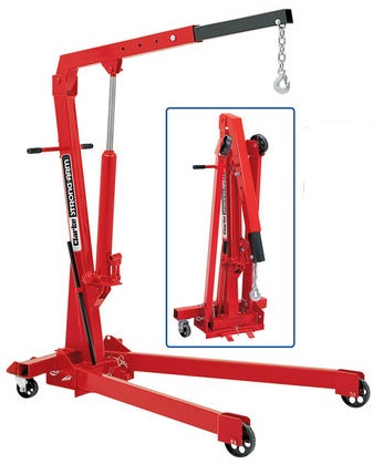
2.2.2 Engine crane and leveller
This is the type of engine crane I use. It has a maximum lift of between 0.25 and 1 tonne depending on extension and seems quite adequate for this size tractor. On one occasion when trying to remove the hydraulics, it lifted the whole rear end off the ground when the gasket was well and truly stuck.
Finding the best place to lift from can sometimes be a little tricky but it does the job.
When not in use it folds up quite compactly.
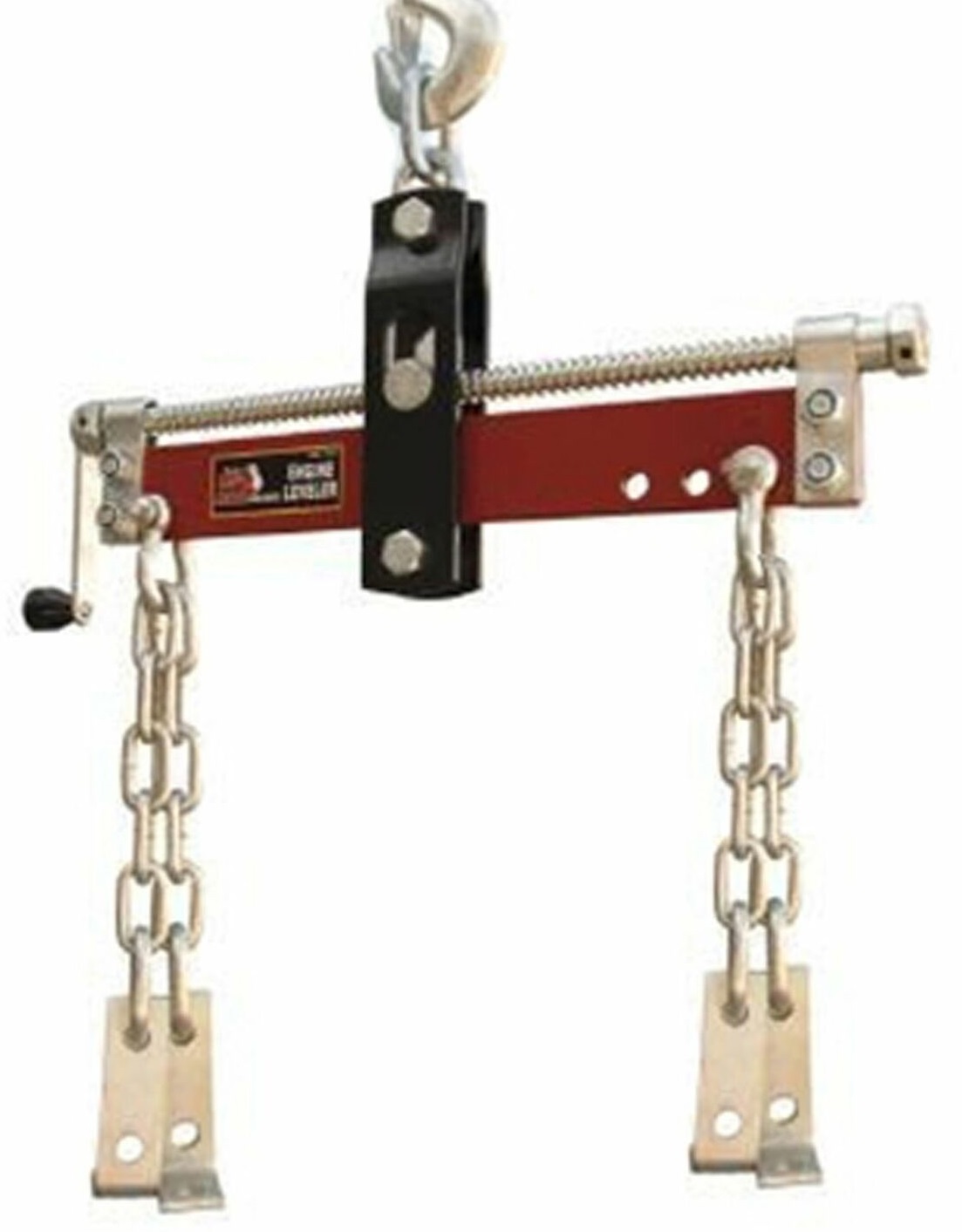
To go with the crane the load leveller is almost a must.
There are a few variants on this general design but this type with the four chains is, in my experience the most versatile.
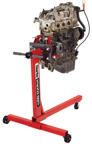
2.2.3 Engine Stand
This is the type of engine stand that I currently use and is the smallest version that Machine Mart sell. It really is too small for the 434’s engine in that I had to make longer arms so it could reach sensible fixing points on the block, but as I’ve had it on free loan for several years, I may as well use it. The engine also needs an extra ½” spacing added to the tubular spacers on the mounting arms to be able to remove the rear crankshaft seal cover for the 434’s engine.
One further problem with this small stand is that, when it comes to rotate the engine, the handle is too short to provide enough leverage with the heavy engine. This isn’t too much of a problem with the cylinder head removed but it is generally a 2-man job to rotate the engine safely otherwise. If I was buying a replacement I’d spend the extra £30 or £40 and get one of the larger versions.
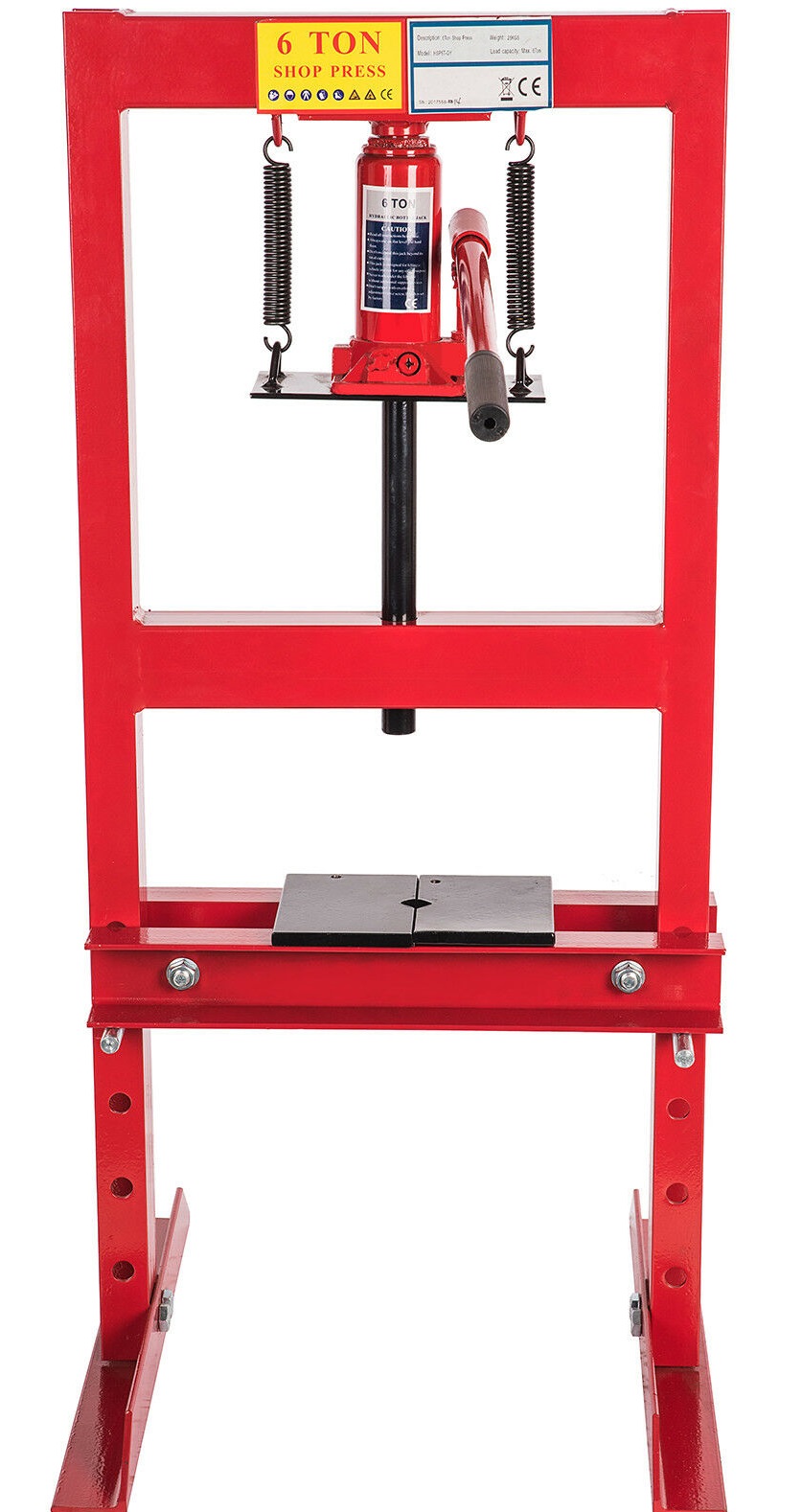
2.2.4 Hydraulic Press
When I bought my first hydraulic press I wasn’t sure if I’d use it much – how wrong I was!
My first press is a 6 tonne version that can either stand on the floor or the bench and is ideal for work on engines and other “smaller” work. There are available on eBay at the time of writing for about £75.
There seem to be small variations particularly in the shape of the black plates in the picture. Mine are simple rectangles, the picture shows ones with a semi-circular cut-out in each while the ones I have with a larger press have “V” shaped cut-outs. I find the “V” shape versions most versatile.
6 tonnes is fine for pressing seals and most bushes & bearings in and out. For some jobs a larger press is needed both for increased height/size of part and resistance.
I also have a 30 tonne press (pictured in my article showing the front axle bush replacement) but that is overkill except for jobs like the front axle of half-shaft bearing removal. These seem to start at about £320 at the moment so is in a completely different price range.
2.3 Measuring Equipment
With plenty of experience it is possible much of the time to assess wear just by feel, but most of us actually need some sensible measuring tools to provide certainty. The following are examples of the more common items that I use regularly.
2.3.1 Steel Ruler
The humble 12” steel ruler has a place in every workshop. It is cheap, quick and obvious to use and is a very useful straight edge – view with a good backlight and one can see imperfections of as little as 0.001”. Check a cylinder head for warp, measure stand-up of liners above a block, look for bent shafts, etc. and a simple steel ruler is an easy answer.
The rulers can be so cheap from places like Toolstation that they can be used as a scraper for removing gasket material from large flat faces… but don’t use the same ruler for precision level checking!
2.3.2 Feeler Gauges
Everyone needs a set of feeler gauges or how else can you set the valve rocker clearances? They also will be needed to check piston ring clearances, stand-up of liners (with the steel ruler) and a variety of other situations where small gaps need to be measured. Imperial or metric isn’t too critical - 1mm = 40thou.
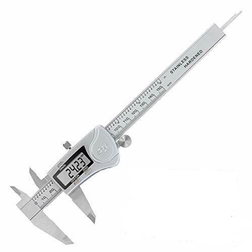
2.3.3 Digital Vernier Caliper
These have become so cheap that most workshops contain at least one set. While some carbon fibre ones are on sale for less than £4, my favourite is something like this one – stainless steel, a large display IP56 protection (good for a dirty environment) and a lithium CR2032 battery. Most units on sale use smaller batteries and I find I’m always having to replace them, but the lithium versions last much longer.
While not as accurate as the micrometers below, the digital caliper is a quick and convenient tool for internal, external and depth measurement.
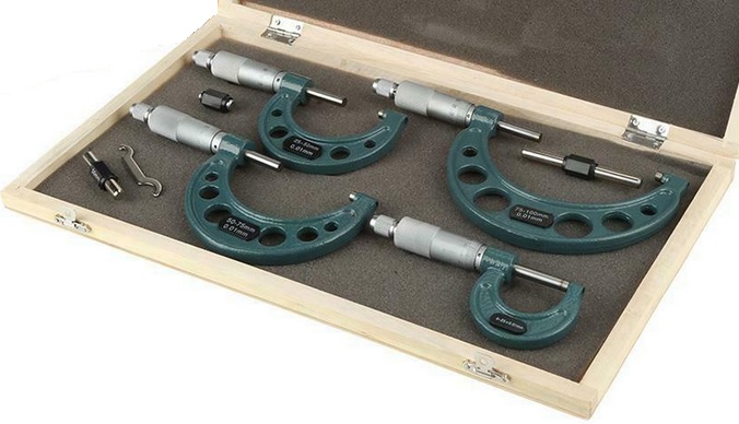
2.3.4 Micrometer
Checking the diameter, ovality and other eccentricity of a crankshaft main or big-end diameter requires more accuracy than can reliably be delivered by a digital Vernier caliper. Cheap Chinese sets like this will measure up to 100m diameter (about 4”) and include test bars (the black and silver bars in the photograph) to confirm the zero point for the larger sizes. Prices start at about £40 on eBay.
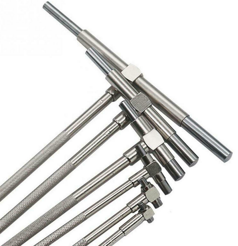
2.3.5 Telescopic Bore Gauge
While the micrometer is ideal for accurate outside measurements, the telescopic bore gauge captures the diameter of a bore using spring-loaded plungers and a twist of the handle to lock their position. The length (and hence the bore diameter) is then measured with a micrometer.
These can also be useful for measuring wear in various places in a bore. By capturing the diameter at a particular point, comparisons can be made in other places to determine wear. Usually, because the gauge can be tilted in a bore, it is also possible to capture a diameter and tilt the tool to extract it through a slightly smaller diameter.
The relatively long handle also makes deep diameter measurements possible.
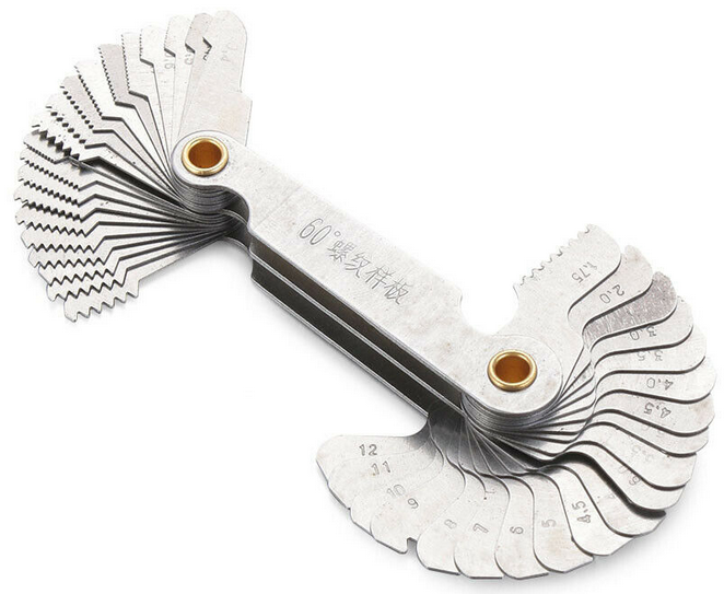
2.3.6 Thread Gauge
At some time or other we all need to determine the size and type of a thread. These simple and low cost tools (Chinese ones start at about £3) have blades in standard imperial and metric pitches. The imperial pitches are in “threads per inch” while the metric are marked directly as pitch in millimetres.
Some imperial threads have a 55 degree thread angle (e.g. Whitworth) while both metric and UNC/F are 60 degree. The gauge may therefore not always match the thread shape but knowing the pitch and diameter (using a digital vernier caliper or micrometer) and using thread tables from the Internet, it is possible to determine the thread.
Putting this issue into perspective, on the 434 the following are just some of the threads used:
- UNC – most nuts and bolts
- UNF – wheel nuts and the nuts to hold the injectors in place
- BSP and BSPT – various oil, fuel and water connections
- Metric – fine pitch metric threads are used on the injectors and CAV DPA pump
- BA – some early electrical fittings
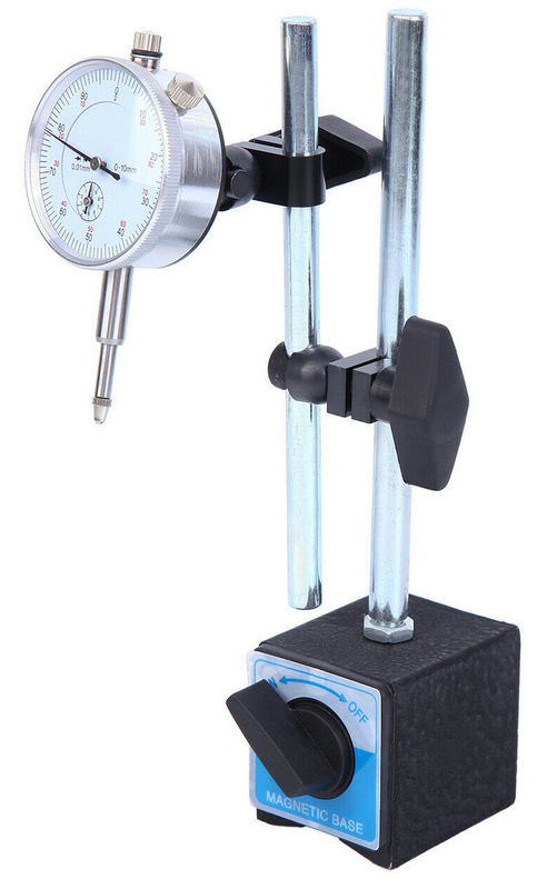
2.3.7 Dial Gauge
A dial gauge, shown here with an adjustable magnetic stand provides high accuracy relative measurement. The metric version has a range of 10mm and a resolution of 0.01mm.
On this gauge, the plunger under the dial moves in and out.
Chinese versions of this part can be found on eBay for as low as £16. Gauges and stands are available separately but there seem to be some good deals buying the two as a set.
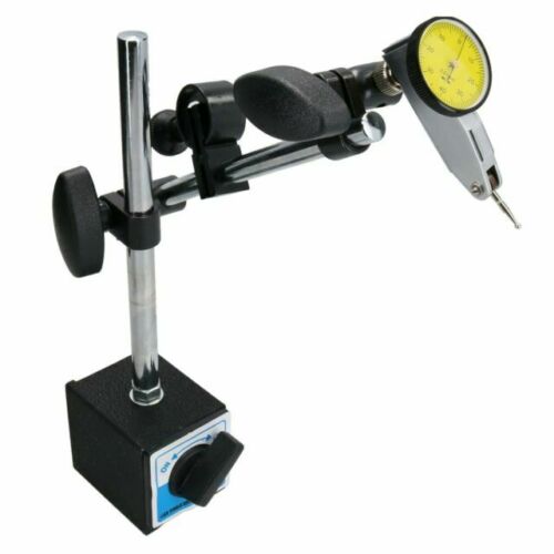
An alternative gauge is the lever arm type shown here. The version I have has the same range and resolution as the previous version but the plunger moves from side to side rather than in and out. Each type has advantages and disadvantages in use but I’ve found this second type to be easier to use for measurements of timing gear backlash while the first type was easier for measurement of valve guide clearance as will be explained in a later article.
3 Before Splitting the Tractor
It is a good idea to clean everything as much as possible. Generally there will be layers of dirt, grease and oil so several cycles of liberal application of degreaser and pressure washing are likely to be needed. Removing the contamination at this stage makes everything more pleasant to work with and reduces the risk of foreign bodies getting into the engine or hydraulics. Getting the bonnet and other tinwork out of the way will help access for cleaning. Ensure that you have plenty of boxes and plastic bags plus a marker pen to label their contents. No matter how well you think you will remember which bolts go where, sensibly grouped and labelled packaging will save confusion when it is time to rebuild. Are there any specific tests that need to be completed before the split? In the case of this tractor tests were needed in two areas:
3.1 Hydraulics
The workshop manual describes a formal test procedure to go through to identify what could include several different problems to investigate and rectify. This will be covered in more detail in the subsequent article on the hydraulics but this has all been done and recorded for this tractor.
3.2 Engine
If it hasn’t been done before, now is a good time to do a compression test. This is described in more detail in the article on How to Diagnose a Smoking Engine. For this engine the results weren’t too bad:
| Cylinder 1 |
450 psi |
| Cylinder 2 |
500 psi |
| Cylinder 3 |
520 psi |
| Cylinder 4 |
510 psi |
The workshop manual quotes the compression at both 200 and 300 rpm for both the BD144 and BD154 engines used in the B250/B275/ 276 and B414/434 respectively as:
| BD144 |
BD154 |
|
| 200 rpm |
330/355 |
445/470 |
| 300 rpm |
350/375 |
510/535 |
The cranking speed wasn’t measured but, from the results was probably just under 300 rpm. It is generally assumed that a spread of up to 10% is normal on a good engine so the 450 psi on cylinder 1 indicates that this is a little on the low side and will warrant further investigation when the engine is dismantled.
The rattle from this engine needed a bit more investigation while it would still run. The nosecone, air cleaner and bonnet were removed to see if they contributed to the noise.
In the following three short video recordings (unfortunately with some wind noise), in addition to the normal diesel engine noise, an abnormal metallic rattle can be hear from time to time.
The radiator and cowl are in place and the metallic sound can be heard.
The radiator has now been removed but the metallic sound can still be heard so fan blades catching the cowl or any resonance in the radiator/cowl is excluded.
Removing the fan blades stops the metallic sound. The fan blades are therefore generating the noise, but as there is no damage to the blades, this must be due to some form of mechanical irregularity transmitted from the crankshaft via the fan belt to the fan. The probability that this is related to the timing gears is therefore reinforced.
4 Removing the Remaining Odds and Ends
Some of the following tasks are likely to spill oil on the floor so it may help to have a plastic sheet or something else down to absorb the mess.
The following tasks can now be
completed:
- Remove the battery.
- Drain the engine oil
- Remove the seat.
- Drain the hydraulic oil. I use a small transfer pump to suck oil out through the inspection cover on the hydraulics unit to get as much oil out as possible
- Remove the high pressure hydraulic pipe (smaller of the two pipes.) There are two Allen screws holding the pipe to the pump and a nut to undo at the hydraulic unit under the seat – this nut doesn’t have much clearance and you may find that not all spanners will fit… I use a metric one as the imperial sizes will not provide enough movement.
- Remove the suction hydraulic pipe (larger pipe.) there are two different sized Allen screws holding the pipe to the pump and a rubber tube joining it to the suction filter.
- Drain the fuel tank and remove along with the battery tray. This isn’t necessary on all the Bradford tractors but with the 434 the top two engine bolts can’t be accessed with the tank in place.
- Disconnect the wiring loom from all points forward of the battery tray.
- Remove the starter motor.
- Remove the firewall.
- Remove the fan and dynamo belts plus dynamo (alternator on this tractor.)
- Remove the remaining fuel lines and leakdown pipe from the injectors.
- Remove the exhaust manifold.
- Remove the inlet manifold and fuel filter.
Not all of these absolutely have to be done at this stage but it helps reduce the engine weight and gets things
out of the way should any form a sling be used to support the engine.
5 The Actual Split
The split is in two parts:
- Removing the front axle and supporting casting (the tombstone.)
- Removing the engine complete with flywheel and clutch from the rear end of the tractor.
Both parts need the remaining
part of the tractor to be supported, initially the engine and rear end then
just the rear end.
5.1 Removing the Front Axle
Disconnect the drag link at the axle end. It can then be rotated out of the way towards the back wheel. The earlier article (Tractor Steering Overhaul – Part 1) provides information on splitting the ball joint if you haven’t done this before or are having difficulty.
Strap the now released ‘L’ shaped arm to the axle beam to keep the wheels straight ahead and stop them moving from side to side. This will make moving the axle and tombstone assembly easier.
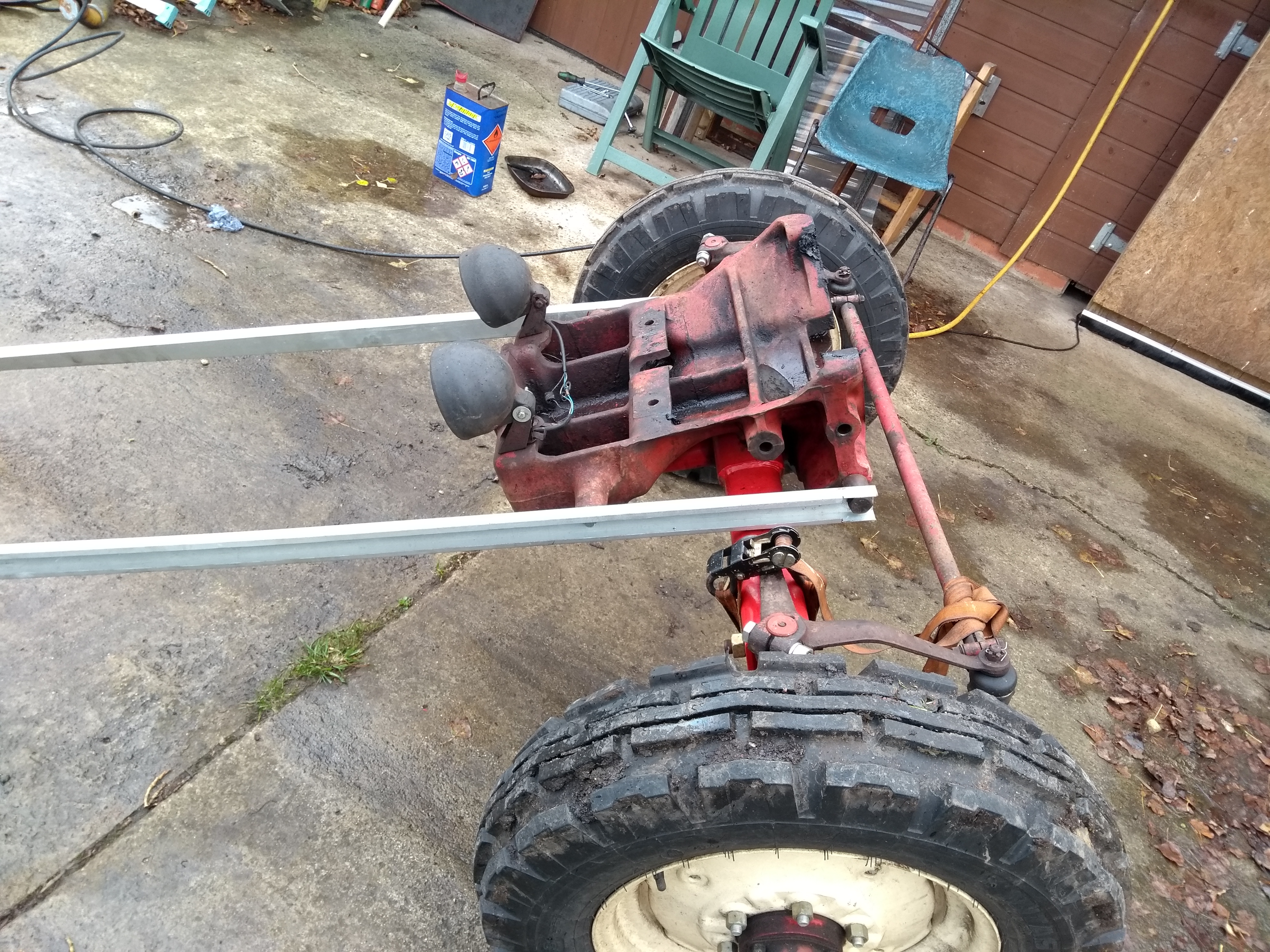
One simple tool that I made is a pair of arms to bolt onto the sides of the tombstone, effectively creating shafts as in a horse cart as shown in this picture. Without these shafts the weight distribution tries to turn the assembly upside down but the shafts and locked steering mean that the whole unit is very easily and safely moved by a single person.
The tombstone is bolted to the engine by 4 bolts (one is longer than the others.)
The engine and all behind it need to be supported so these bolts can be removed and the front axle assembly wheeled away. There are a couple of ways this can be done:
- Use the engine crane from the side to take the weight. The difficulty is finding somewhere to take this load. Looking online and considering the 3/8” UNC bolts that hold the rocker box cover, a grade 5 (which is probably a reasonable assumption for the stud) can take about 6600 lbs (about 3 tonnes) before it permanently elongates so a single bolt should be able to support the whole tractor’s weight. Using both bolts and the load leveller should be a conservative solution.
- Jack under the front edge of the transmission casting. There is space in this area to fit a trolley jack but it is difficult to provide additional support to get the jack out later.
My solution was to use both methods at the same time. The engine crane and leveller took the main load while the trolley jack was there as a safety backup… and this approach makes the later tasks easier as will be seen.
When splitting these heavy lumps one wants to ensure that the engine crane is in balance, carrying the weight that will remain but not lifting or loading the front axle. This is relatively easy to judge if the 4 bolts are loosened enough to show a small (1-2mm) gap between the tombstone and the engine. Adjust the lift so the gap top and bottom is approximately equal and the load is balanced.
Remove the 4 bolts and the front axle assembly can simply be wheeled out of the way. All this becomes and easy one-man task.
5.2 Removing the Engine
Splitting the engine from the transmission follows a similar process. The engine is already hanging from the crane and the transmission potentially supported by the trolley jack. With the transmission weight supported by the jack and the engine by the crane, the same method of slight loosening of the bolts and equalising the gap top and bottom could allow the engine to be removed. There is however a slight problem with this approach. As the engine is moved, drag as the clutch is disconnected could move the transmission on the jack and snag… and the jack isn’t a sensible long term support for the transmission.
A solution that I haven’t seen elsewhere is this support frame that I made from odd pieces of angle that I had around. It bolts to pairs of holes available in the transmission casting to mount a front loader and has a pair of heavy swivel casters so it can be moved around. The final touch for me was to mount a tow-ball hitch so with the fitting horizontal it became a towbar rather than a stand.
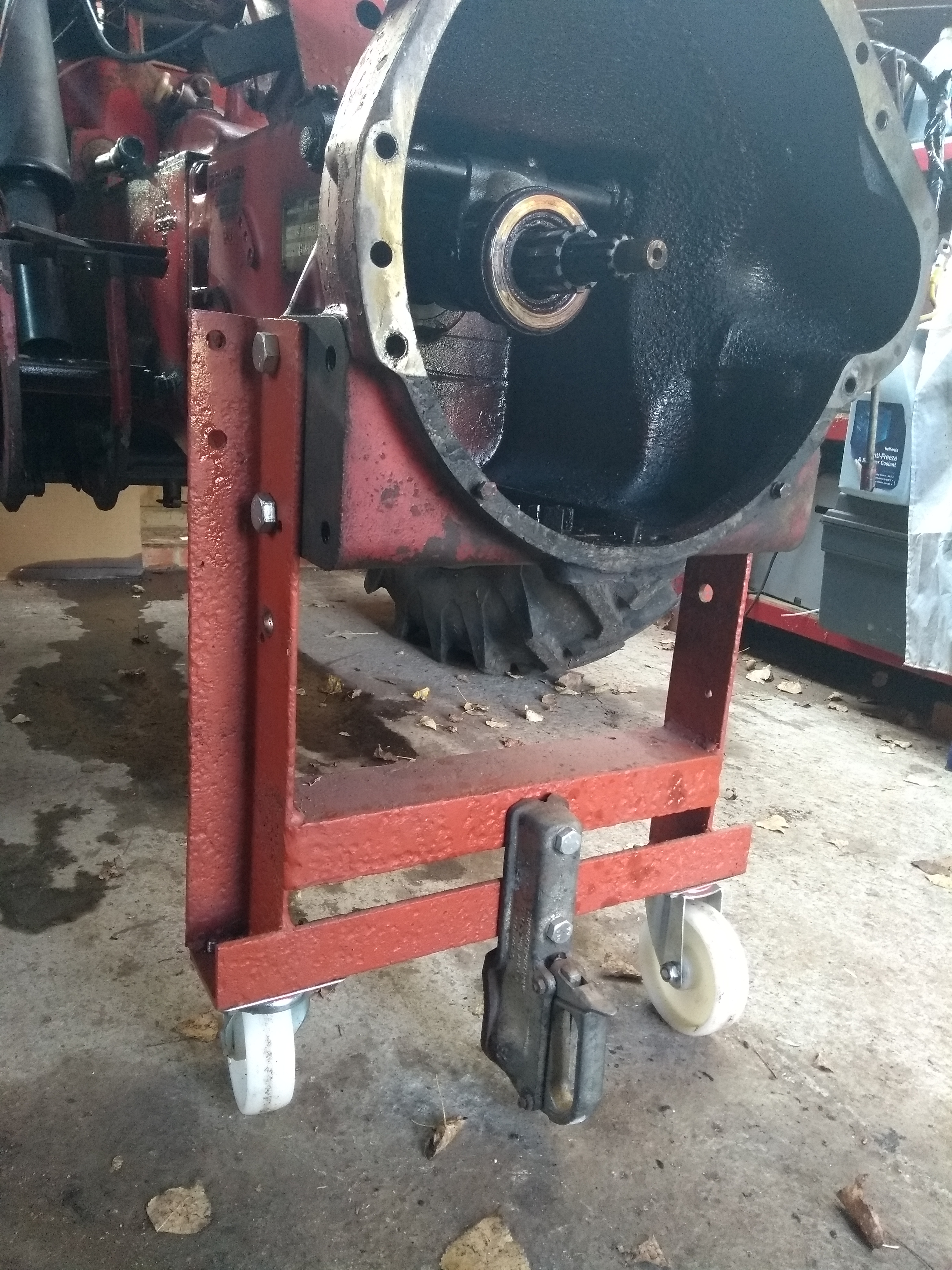
This fitting was actually used to take a rear end to the Gloucestershire Vintage and County Extravaganza a couple of years ago where it was used as a gate guardian on the IH club stand and took part in the tractor parade behind this 434.
With the front of the tractor still supported by the engine crane, the trolley jack was replaced by this stand and the engine crane lowered. As when removing the front axle, the engine mount bolts were all loosened slightly while watching the split line and adjusting the crane level to maintain an equal gap. The load leveller needs to be adjusted as part of this process – a bit of a guess trying to pick the balance point but the engine is tail heavy due to the flywheel and clutch.
There are a couple of dowels between the two castings so the engine normally needs to be wriggled slightly from side to side to get them to part. Care is needed at this point in case the leveller isn’t balanced and it may need a hand to stop the load tipping as it finally cones free. The engine crane was then wheeled away with the engine, flywheel and clutch.
Continued in part 2 with the initial engine strip and assessment…
ARTICLE CONTRIBUTED BY ANDREW CHAPMAN
© ANDREW CHAPMAN & ANGLO AGRIPARTS LTD


Licence Terms
You are free to: Share, copy & redistribute the material in original format for any purpose as long as you follow the license terms below:
- Attribution – you must give appropriate credit and provide a link to the original article in a reasonable and visible manner
- You may not in any way suggest that the licensor endorses you or your use.
- No Derivatives – The material must be distributed in full, including disclaimer, you may not distribute or share modified material.
- No additional restrictions – You may not apply legal terms that legally restrict others from doing anything the licence permits.
- No warranties are given. The license may not give you all of the permissions necessary for your intended use. For example other rights such as publicity, privacy, or moral rights may limit how you use the material.
Disclaimer

Related Articles

International Harvester 434 Major Works Part 2 - Cylinder Head Overhaul
Contributor Andrew Chapman undertakes a major overhaul of his International Harvester 434. In part 2 he covers the cylinder head and valve overhaul.
-200x200.png "International Harvester 434 Major Works Part 3 - The Oil Filter That Didn't")
International Harvester 434 Major Works Part 3 - The Oil Filter That Didn't
An oil filter is meant to filter oil and this engine didn’t filter oil at all. Read Andrew Chapman's article as he investigates the issue with his BD154 engine on an International Harvester 434.

International Harvester 434 Major Works Part 4 - Strip, Clean & Initial Inspection
In Andrew's latest article he focusses on the stripping, cleaning and initial inspection of the various components fitted to the engine block on his International Harvester 434.