Tractor Steering Overhaul Part 3 - Front Axle Pivot

Steering Overhaul Part 3 - Front Axle Pivot
This article is based on rebuilding the front axle pivot pin and bushes on Bradford built International Harvester B275, B414 and 434 tractors. The design of the parts are however similar to those on many tractors of the period and so should be of general use.
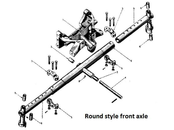
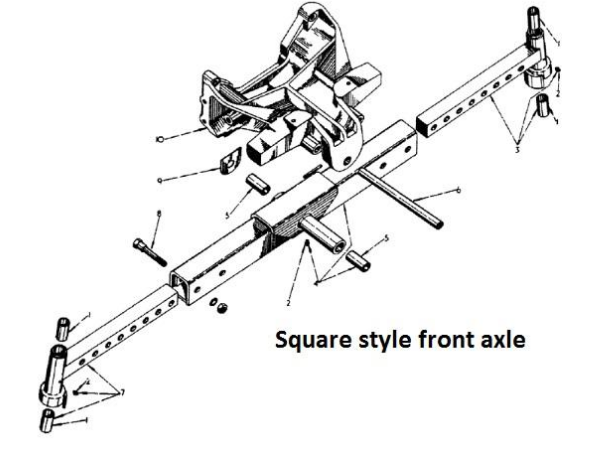
Two different style axles were fitted to these tractors. The round style axle was fitted to both B275 and 276 tractors while the square type was used on the B414, 434 and 444
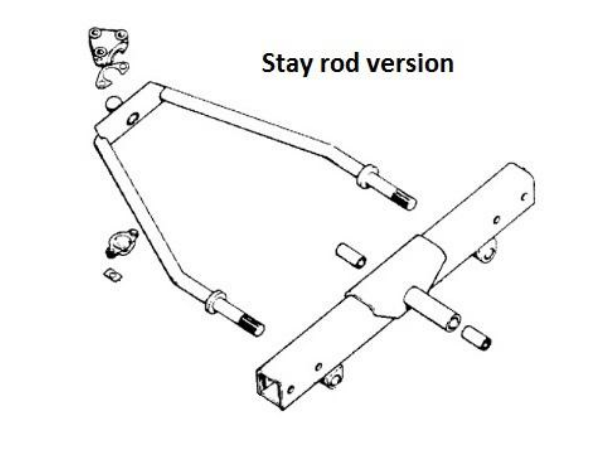
Versions were also made with an additional stay rod to make the whole assembly stronger, but this style isn’t very common.
All styles use the same pivot pin and pair of bushes, or at least these parts can be used to replace slightly different versions fitted to the B275.
A number of different front support castings (tombstones) were fitted over the years but the only assembly difference between the B275 and later models is that it held the pivot pin in place with a grooved roll pin while the later tractors used a 3/8” UNC x 4-1/2” or 6-1/2” bolt depending on the casting
The pivot pin should be light press fit into the support casting and has a tapped hole (1/2” UNC although some aftermarket parts use M12) in the front to allow removal.
One or more shims are fitted between the rear of the axle and the support casting to take up end float. A single phosphor-bronze or brass shim abuts the axle with steel shims between it and the casting as necessary to take up any additional clearance.
A single grease nipple is provided under the centre of the axle. This is sometimes broken off and is often overlooked when it comes to greasing, one of the most common causes for pivot pin wear.
As mentioned earlier, the stay rod version of the axle isn’t very common so when these tractors with standard axles are used with a front loader they are much more prone to wear.
Assessment and Repair
While the pivot pin can be removed to drop the axle from the tractor, it is often easiest to remove the bonnet and radiator then unbolt the front support casting. Support the engine and rear of the tractor on blocks and the front casting with an engine crane or similar before removing the bolts.
The casting is only held on with 4 bolts and it is much easier when reassembling to realign the axle, casting pin and shims with the casting off the tractor and inverted.
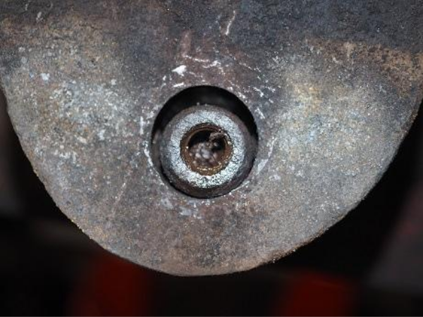
The most important area to check for wear is where the axle pin fits in the front of the support casting.
This photograph shows a pin that hadn’t been greased and subsequently seized in the axle bushes. It then sheared the retaining bolt and used the casting as its bearing leading to a badly worn hole. Always therefore make sure that the grease nipple is fitted and not blocked.
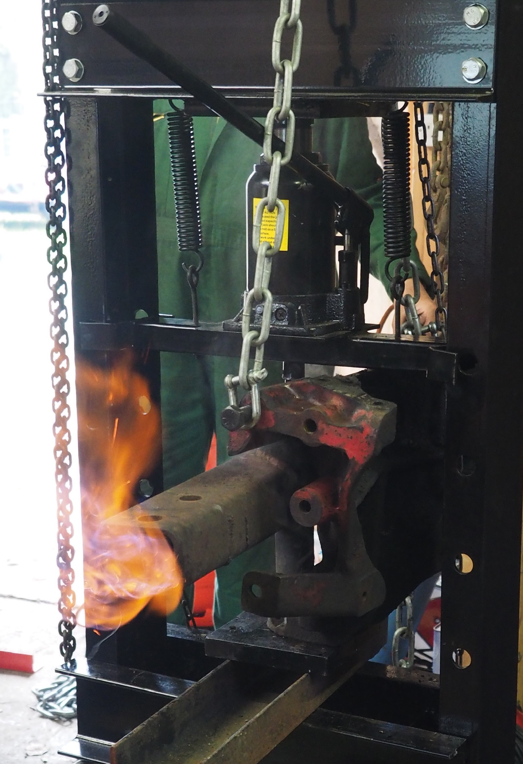
To give an example of how tight this pin can stick with this level of neglect, this photograph shows the casting and axle in a 30 ton press where the pin still wouldn’t move. Eventually it took a 50 kW gas torch to heat the centre of the axle while at the limit of the press before it would move.
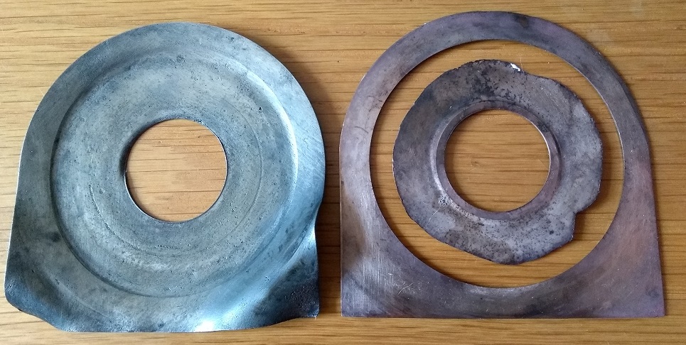
This photograph shows the shims that came out of the above tractor. Both started life as flat – the steel one has been bent while the phosphor-bronze one has been worn through.
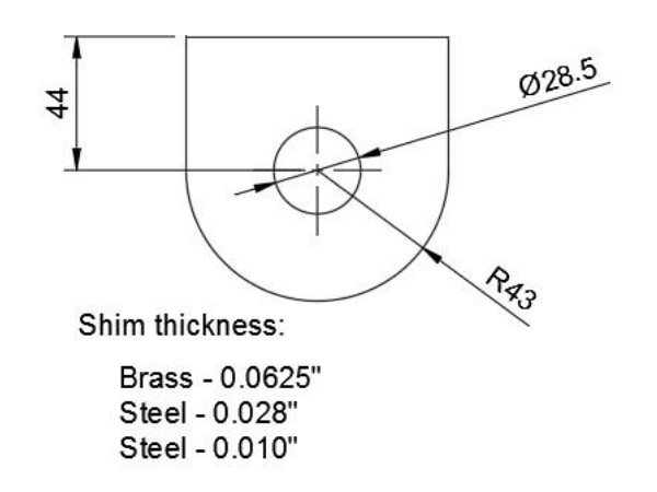
This diagram shows the nominal sizes for the shim. The top edge fits against a machined edge on the support casting to stop the shim turning and so the 44mm dimension is the most critical.
Standard shims in the parts list are with the thicknesses shown here. If you have to make your own, this drawing should provide a starting point.
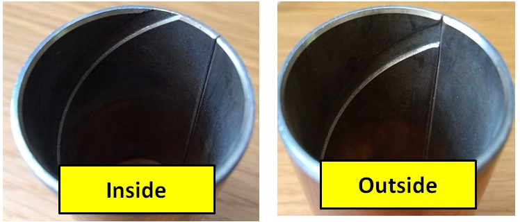
The two bushes fitted to the axle are similar to these – they are actually spares for the axle extensions but the axle ones are similar, differing only in dimensions.
As with the axle extension bushes mentioned in the previous article, there is a right and wrong way to fit them. Read that article for suggestions on how to remove the axle bushes. If you use a tap, a 1-1/4” UNF or UNC taper tap works well. The bush may need reaming – some do but not all depending on supplier.
There are also plastic bushes on the market. Having tried one set I was not impressed – they are difficult to fit because they barrel out when pushed in so really need an alignment sleeve making to help with insertion. I’m also not convinced that they will last anywhere as long as the original design.
If you need to ream the metal bushes then an expanding reamer will be needed. Most of the readily available ones are too short to ream both bushes at the same time, which is what should really be done to ensure that they are truly inline.
My solution is shown here. An old axle pivot pin was cross-drilled to take a handle then bored out to take the shank of the reamer which was fixed with a roll pin. The extension therefore is a reasonable fit in the intended finished bush size so with care it is possible to get the bores aligned.
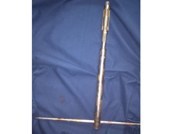
If you’ve never used a reamer before, always only turn it clockwise, never backwards as this will damage the cutting edges which are usually glass hard. You can push the reamer in and out (hand force only) when preparing to take a new cut – I tend to go for 1 or 2 thou at a time adjusting and measuring across the cutters with a micrometer, not a vernier caliper, for accuracy. When you’ve finished with the reamer, oil or grease it and wrap in oil-paper or cling film to protect the edges from damage and rust. The standard finished bore is 1.118” – 1.120” with the pin being 1.115” to 1.116” although I’ve had undersized pins supplied in the past so it is worth checking them before starting work.
Coping with a Worn Casting
Worn bushes, axle pin and shims are relatively straightforward to fix but oversize holes in the support casting are a bigger headache.
The standard pin is 1.115” to 1.116” or 28.32 to 28.35mm. On my 434 there was some play in the casting and, as there is a reasonable thickness of lining in the bushes, I used a length of 30mm stainless steel (303) bar which was conveniently available on eBay. I then reamed the casting and bushes to fit this bar which was machined to match the original pin except for the larger diameter.
Where there is more wear, I’ve heard of people reaming the casting out to press in bushes to bring the holes back to their nominal sizes but I’ve never tried it. As the holes tend to wear very oval I have my doubts about this as a good solution but others may have different views.
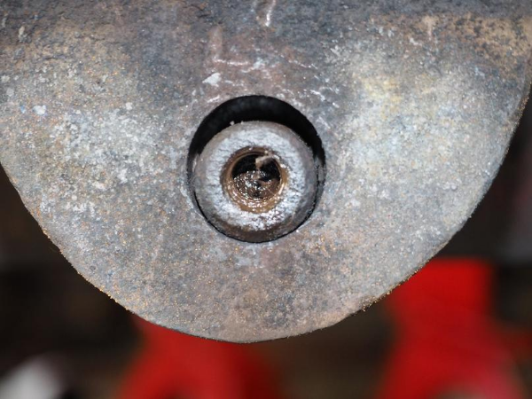
The real solution is to have the casting line bored, bushes made and fitted then reamed to size again. This photograph is of the B414 that had the pin seized in the axle (earlier photograph with the flames.) As can be seen, the casting has worn a lot and is noticeably oval. Most of us don’t have the equipment or skills to carry out this level of remedial work so it was passed to a local specialist.
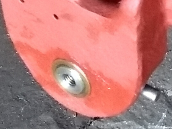
This second photograph shows the same casting after it has been line bored and a bush fitted. A pin (visible at the right of the image) passes through casting, bush and pin to lock everything in place.
Reassembly
Assuming the support casting was removed from the tractor, it is easiest to reassemble with the casting and axle inverted. If as part of a more major overhaul, it is also easiest if the axle extensions aren’t fitted yet.
While all of this can be done supporting everything by hand, if an engine crane and leveller is available it is much easier to get everything back together.
Don’t use a steel hammer to knock things into place, only a soft faced (e.g. hide or copper) tool.
Check that the shims fit flush with the inside edge of the support casting with just the axle pin in place – if they don’t fit at this stage the next stage will be impossible to complete.
Lower the axle into position and gently tap the axle pin through the front of the support casting and most of the way through the axle. The axle should be pushed towards the front of the support casting, the phosphor-bronze shim inserted and the remaining gap filled with steel shims. Aim for less than 0.5mm end float – the less the better. Look through the back of the casting to check that everything is perfectly aligned and tap the axle pin further into place, rotating it with a screwdriver or other tool to ensure that the cross drilling is horizontal. Tap it fully home and then using a tapered round bar, ensure that the securing hole in the pin lines up with the casting. Fit the securing pin or bolt.
The support casting can now be turned the right way up and mounted back on the tractor. An engine crane and leveller make this easier.
DON’T FORGET TO GREASE THE PIVOT PIN REGULARLY.
ARTICLE CONTRIBUTED BY ANDREW CHAPMAN
© ANDREW CHAPMAN & ANGLO AGRIPARTS LTD


Licence Terms
You are free to: Share, copy & redistribute the material in original format for any purpose as long as you follow the license terms below:
- Attribution – you must give appropriate credit and provide a link to the original article in a reasonable and visible manner
- You may not in any way suggest that the licensor endorses you or your use.
- No Derivatives – The material must be distributed in full, including disclaimer, you may not distribute or share modified material.
- No additional restrictions – You may not apply legal terms that legally restrict others from doing anything the licence permits.
- No warranties are given. The license may not give you all of the permissions necessary for your intended use. For example other rights such as publicity, privacy, or moral rights may limit how you use the material.
Disclaimer

Related Articles

Tractor Steering Evaluation
Contributor Andrew Chapman carries out a steering evaluation referencing IH Bradford built tractors.

Tractor Steering Overhaul Part 1
Contributor Andrew Chapman compares the various methods for splitting swivel joints on steering overhauls.

Tractor Steering Overhaul Part 2
Part 2 of Andrew Chapman's steering overhaul review. This article is based on rebuilding the steering knuckles and hubs on Bradford built International Harvester B275, B414 and 434 tractors.

Tractor Steering Overhaul Part 4
The final article in the 'Steering Overhaul' series by contributor Andrew Chapman. This article focuses primarily on steering boxes fitted to Bradford built International Harvester tractors.

Ferguson TED20 - Dismantling the Front Axle - Video Tutorial
Ferguson TED20 - Dismantling the Front Axle - Video Tutorial. Gordon removes the front axle in order to inspect it's condition in preparation for the next stage of the restoration.

Ferguson TED20 - Removing the Axle Pivot Pin - Video Tutorial
On inspection Gordon discovers the axle pivot pin isn't in the condition he hoped. Here Gordon guides us through the process of removing the axle pivot pin on his TED20 restoration project.

Ferguson TED20 - Removing The Steering Box - Video Tutorial
The steering box contains the gears that transmit the driver's steering movements to the steering linkage that turns the wheels. In this video Gordon investigates steering issues on his TED20 - part 1 follows the step-by-step removal of the steering box.
Tags harvester, international, bradford, steering, tractor