
The third in the series of articles focusing of dynamos from Andrew Chapman. Andrew's knowledge and love for tractors originates from his time growing up on a dairy farm. With a degree in engineering Andrew applies his extensive skills to pursue his interests in tractor restoration. Andrew is currently restoring International Harvesters ’61 B275, ’67 B434 - and has contributed to the International B Series Tractors Group and a number of instructional files to the International Harvester Club of Great Britain.
Dynamo Internal Fault Finding
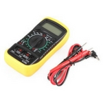
This describes fault-finding on a Lucas non-vented dynamo as shown here but the same principles apply to almost all dynamos. All the electrical testing was done with a very cheap digital voltmeter (DVM) available at the time of writing for less than £6 delivered including leads and battery. This one even has a backlight. This meter isn’t accurate enough for precision electronics work but is quite adequate for almost all tractor electrical fault-finding. Its voltage accuracy is ok, current measurements normally require something with a higher range (but there are simple work-arounds so high current testing isn’t needed) and its resistance ranges are a little insensitive at the lowest settings… but one could spend 20 or 30 times as much and not get anything much more useful. Almost any meter with a 2V and 20V DC range plus 200 ohm (or lower) and continuity ranges would do all that is needed.
Introduction
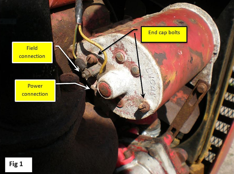
Dynamo connections can be via ring tags as shown here or crimps.Some dynamos were non-vented as in this example (Fig 1.) The sealed enclosure provided enhanced protection against the hostile environment that a tractor may be subjected to but at the expense of reduced output. Typically this type is rated at about 11 Amps.
Vented dynamos (typically fitted to cars and some tractors in the 50’s and 60’s) have holes in the castings at each end of the dynamo to allow air to be drawn through, usually enhanced by a fan between the pulley and dynamo body. The differences in cooling resulted in this type being rated significantly higher at 22 Amps or more.
A simple dynamo check is to disconnect both field and power connections ensuring that they don’t short to surrounding metalwork in case there is also a regulator fault. The tractor is started at low speed (about 600 RPM), the voltage between power and ground measured (typically often 2 to 4 volts), then the field and power terminals linked. The voltage should rise (possibly to around 8 or 9 volts.) Raise the engine speed slowly and the voltage should rise – take care not to exceed 20 volts or there is a risk of damage to the dynamo’s insulation. If the above works then the dynamo is capable of providing power although this test doesn’t confirm that it can deliver its full rated output current.
If this doesn’t work, the dynamo may need re-polarising… resetting its residual magnetism. This is also sometimes necessary if the tractor’s battery polarity is changed for any reason. To do this, connect a wire to the non-earth side of the battery then quickly touch the other end to the field terminal – a fraction of a second is all that is necessary then repeat the simple dynamo check above.
For the dynamo being described here, the above still resulted in no output so the dynamo was definitely faulty and needed an internal investigation.
Removal
While removal of the dynamo may seem simple (it is sensible to disconnect the battery first), there is one potential problem that may be encountered at this stage.
The early dynamo end castings were made of what was known as ‘pot’ or ‘monkey’ metal… or some other less complimentary terms. ‘Pot’ metal is a mix of a wide variety of non-ferrous metals that could include aluminium, magnesium, tin, lead, copper and all sorts of impurities as non-specific scrap was just melted together in the same pot and then cast. Car door handles and hinges of the time used the same materials and many will remember how some bubbled under chrome and were also prone to break. These early dynamo castings share the same shortfalls in that few shared the same alloy mix, could have various inclusions leading to weak spots. Over time and due to corrosion the casting could grow onto fixing bolts making the dynamo difficult to remove.
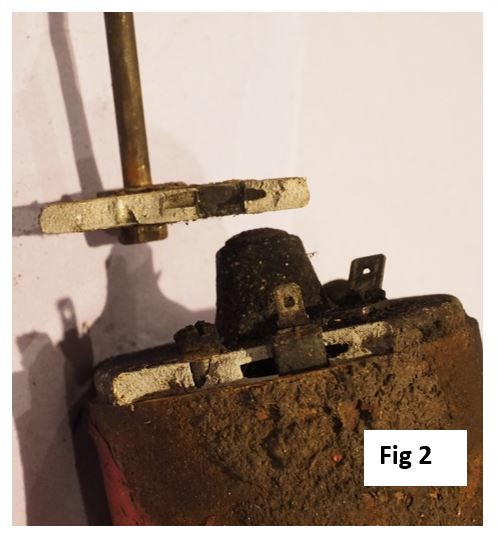
This photograph shows a broken end casting from a different dynamo. The long top mounting bolt had seized into the casting and a quite light tap broke the casting into two. The fracture line is very thin in places and, not clear in the photograph, there were small inclusions in the fracture line.
So, DON’T TRY TO KNOCK OUT THE TOP BOLT. If the bolt is tight then it is probably best to remove the dynamo with bracket so the bolt can be carefully removed on the bench.
Investigation
The dynamo was removed then rotated by hand to confirm that the bearings seemed ok… which they were. The dynamo pulley should turn freely with just a slight drag due to the brushes on the commutator. If the pulley is stiff to turn then it will need to be removed and the bearing replaced when the end covers have subsequently been removed. Generally it is easier to remove the pulley, if necessary, before further dismantling the dynamo.
Unless the bearing needs replacing then the pulley doesn’t need to be removed.
- The end cap was removed after unscrewing the two end cap bolts. This normally needs a large screwdriver with its blade in good condition as these bolts tend to be difficult to remove
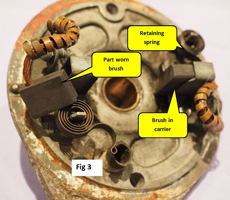
- The carbon brushes were checked for wear and seamed ok – these brushes were still about 2/3 of their original length.
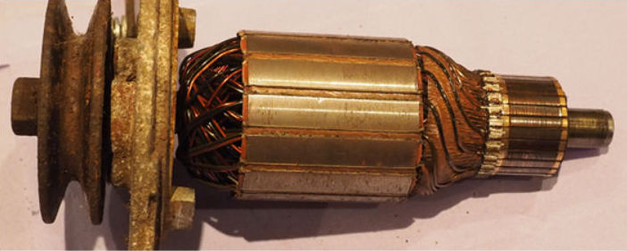
- The armature was checked by first looking for burning, scoring or other damage – it looked ok.
- The resistance was measured between adjacent armature segments looking for any significant difference in readings – a disconnected or shorted winding would be expected to give a difference of 40% or more from the normal readings. Again everything looked ok. Using the multimeter shown earlier, a typical reading on this armature was about 0.6 or 0.7 ohms – the accuracy of reading is poor but good enough to show if one or more windings are disconnected (higher than normal reading) or shorted (lower than normal reading.) If a wire is disconnected then re-soldering it at the commutator may be all that is necessary. A short, unless there is an obvious solder bridge between adjacent commutator segments, most likely needs a replacement armature with a replacement dynamo likely to be the lowest cost solution.
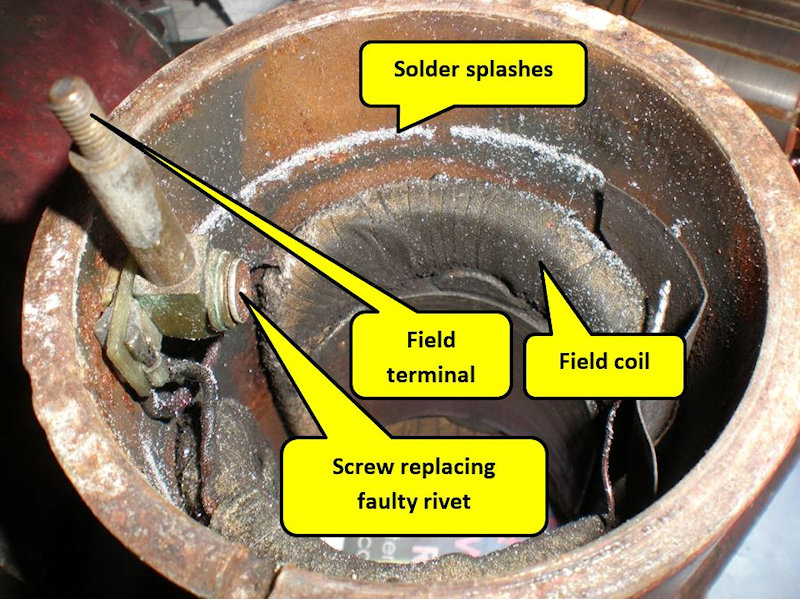
- The resistance between the field terminal and case was measured. This time however the test indicated a problem – the field coil was open circuit indicating that it had either burnt out or that it’s earthing rivet wasn’t making a good connection. Examination of the rivet showed corrosion so it was drilled out, corrosion cleaned and then replaced with a nut and bolt – electrical continuity was then restored. The field terminal to case then measured about 6 ohms.
- The dynamo was re-assembled and successfully re-tested.
- The dynamo now produced power but its regulation was poor and erratic. The voltage regulator was replaced with one bought via the internet quoted as the correct part for the tractor, a description which was only partially correct. The regulator would work with the dynamo but was actually for a vented version in that its nominal current was 22, not 11 Amps, pushing out a good 30 Amps when the engine was first started. The regulators are intended to allow higher charging currents when everything is cold to help recharge the battery after cold starting demands then, as the regulator heats up, the maximum current is reduced.

In UK temperatures there didn’t seem to be much of an overheating problem with running the non-vented dynamo at these higher currents and the tractor was been run in this configuration for a couple of years without problems. Seeing 30 Amps charging from a tractor dynamo may however surprise some people. For peace of mind however the dynamo is then dismantled and re-inspected.
Inside the dynamo case as found a ring of tiny splashes of solder radially out from where the commutator segments are soldered to their armature windings. The solder possibly had only softened with heat rather than completely melted, but it had been enough that all bar the minimum solder needed to maintain the joint had been thrown off.
ARTICLE CONTRIBUTED BY ANDREW CHAPMAN
© ANDREW CHAPMAN & ANGLO AGRIPARTS LTD


Licence Terms
You are free to: Share, copy & redistribute the material in original format for any purpose as long as you follow the license terms below:
- Attribution – you must give appropriate credit and provide a link to the original article in a reasonable and visible manner
- You may not in any way suggest that the licensor endorses you or your use.
- No Derivatives – The material must be distributed in full, including disclaimer, you may not distribute or share modified material.
- No additional restrictions – You may not apply legal terms that legally restrict others from doing anything the licence permits.
- No warranties are given. The license may not give you all of the permissions necessary for your intended use. For example other rights such as publicity, privacy, or moral rights may limit how you use the material.
Disclaimer


