International Harvester 434 Major Works Part 2 - Cylinder Head Overhaul

International Harvester 434 Major Works Part 2 – Cylinder Head Overhaul
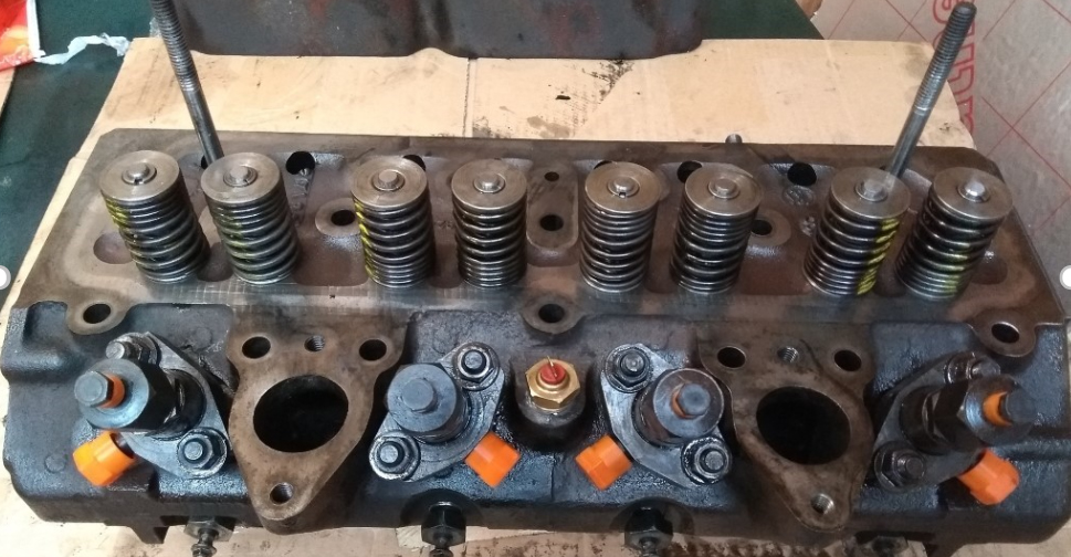
This article describes the inspection and overhaul of an International Harvester 434 cylinder head. This is the same as fitted to all the BD154 engines (tractors B414, 434, 444, etc.), differs only in the double valve springs vs single springs on the BD144 engines (B250, B275, 276, etc.) but is similar enough to most makes of engines. This is therefore likely to be of more general interest.
While in this example the engine was removed first, there is no reason why this task couldn’t be done on the tractor, e.g. when replacing a blown head gasket or as part of a more major repair.
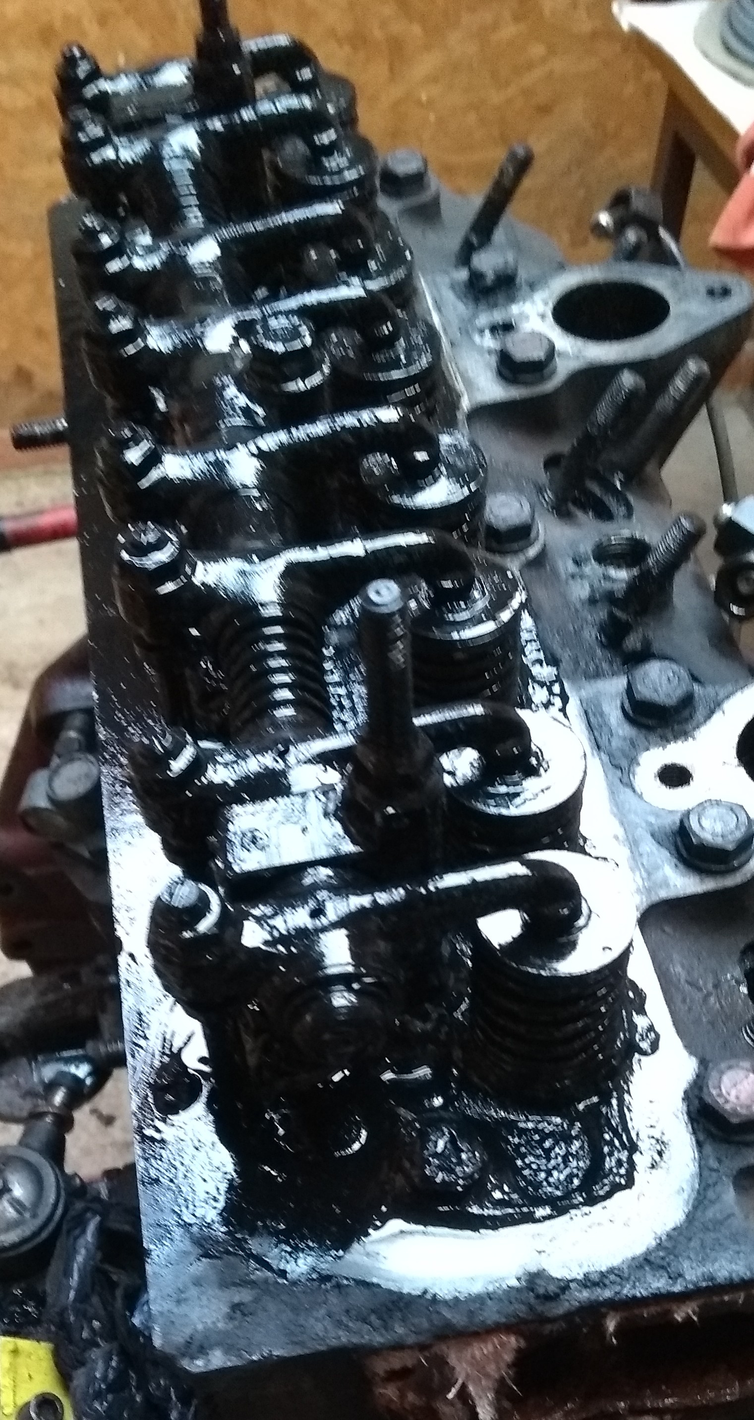
Despite this engine having had annual oil changes for the last 3 years and doing about 100 hours of work per year, the rocker shaft, springs and valves were covered with thick sludge – the worst I’ve ever seen. Clearly it was overdue for attention!
Some of the procedures described below require certain special pieces of workshop equipment. If you don’t have access to them and your cylinder head needs the work, it may be more cost effective / cheaper to simply replace the whole cylinder head. Alternatively you may need to get the work done by an engine specialist.
Rockershaft Removal and Inspection
The first step was to remove the rocker shaft. On most engines this is straight forward but these engines have a twist – the rocker shaft is in two halves and, if you’re unaware, when removed the springs will send various parts flying around the workshop.
With the two nuts that hold the rocker shaft in place and the central cylinder head bolt removed, the whole assembly can be lifted off the studs while pushing the ends together to compress the springs. With it down on the bench, gradually releasing the pressure will allow everything to come apart in a controlled manner. Alternatively everything can be wired or tied together before removing.
The pushrods can be removed and cleaned. Some people recommend that these are kept in order so they can be returned to the same position when the engine is re-assembled due to wear patterns but personally I don’t think this is too critical.
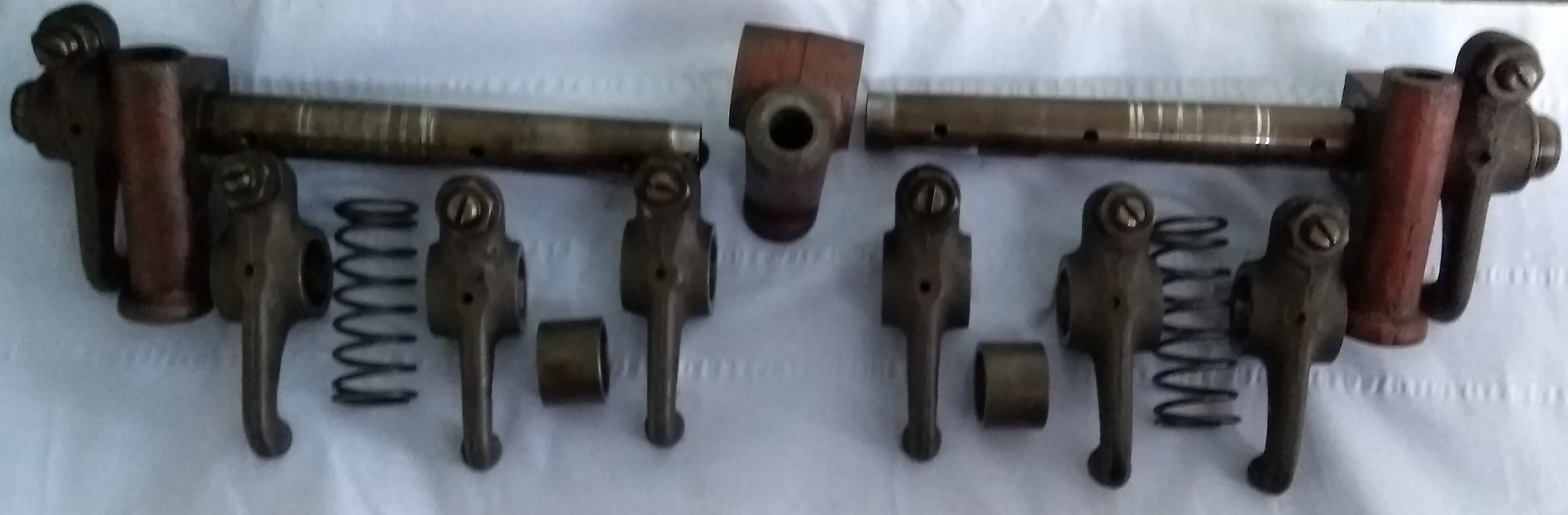
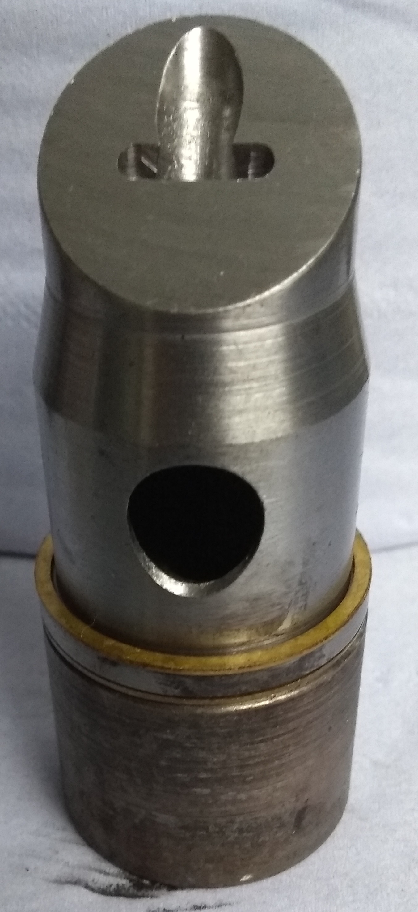
With the rocker shaft removed and cleaned, its construction becomes more apparent. The central red part is held in place by an extra-long cylinder head bolt and, as will be discussed in more detail when the cylinder head is replaced, leads to additional complexity when torqueing the cylinder head back down.
The oil feed to the rocker shaft is also via this central part, into the rocker shafts and then passed to each rocker via holes that can be seen in the photograph. Ensure that all these oil paths are clean.
It is relatively easy to measure the shaft wear with a micrometer. The standard shaft diameter is 0.748/0.749” or 19.00/19.02mm. First ensure that your micrometer correctly zeros – if it doesn’t then adjust the zero either as described in its documentation or search for online videos for help. Check an unworn part of the shaft and confirm the diameter which should be to the above specification. Now measure the shaft where each rocker pivots in turn, measuring from the bright (worn) face on the underside to get the minimal size. On my shafts these were consistently 19.01mm so well within specification. At this time there don’t seem to be replacements available so, in the unlikely event that a shaft is badly worn then the only source will be from a breaker.
The rocker bores can be measured with a bore gauge and micrometer but this isn’t the easiest task to master. As this clearance isn’t anywhere near as critical as the valve guides, working by feel is probably good enough. With the rocker and shaft clean and a minimal film of oil (e.g. WD40), the rocker should rotate smoothly without any stiffness. Now, with the rocker in its operating position, try to move the rocker forwards and backwards – there should be no noticeable movement. Finally, try to twist the end of the rocker which acts on the valve from side to side – there will normally be a just perceptible movement in the end of the arm. If there is too much movement here then it risks reducing oil pressure to the rest of the engine.
Check the rocker arm’s face where it acts on the valve – if the faces are ridged (mine were) then small imperfections can be removed with a carborundum stone or diamond file. Leaving a ridge in place will make it more difficult to adjust valve clearances later.
On my engine the rocker arms were reusable but spares are available – A68047. The replacement part does not include the adjusting screw and nut.
Injector Removal
If they haven’t been removed already, it is easier to do so before the cylinder head is removed.
With the two securing nuts removed, using a pair of heavy screwdrivers or levers between the injector mounting ears and the cylinder head, it should be possible to work the injector out of the hole. Special slide hammers are available on the internet that screw into the leak-off hole in the injector – I do have one of these that I’ve used occasionally but normally the screwdrivers will work ok.
There is a copper washer around the injector nozzle – it usually comes out with the injector but could still be left in the pre-combustion chamber holder.
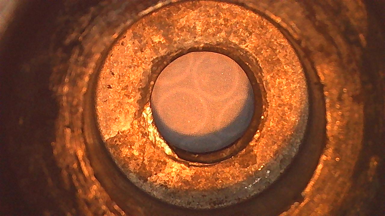
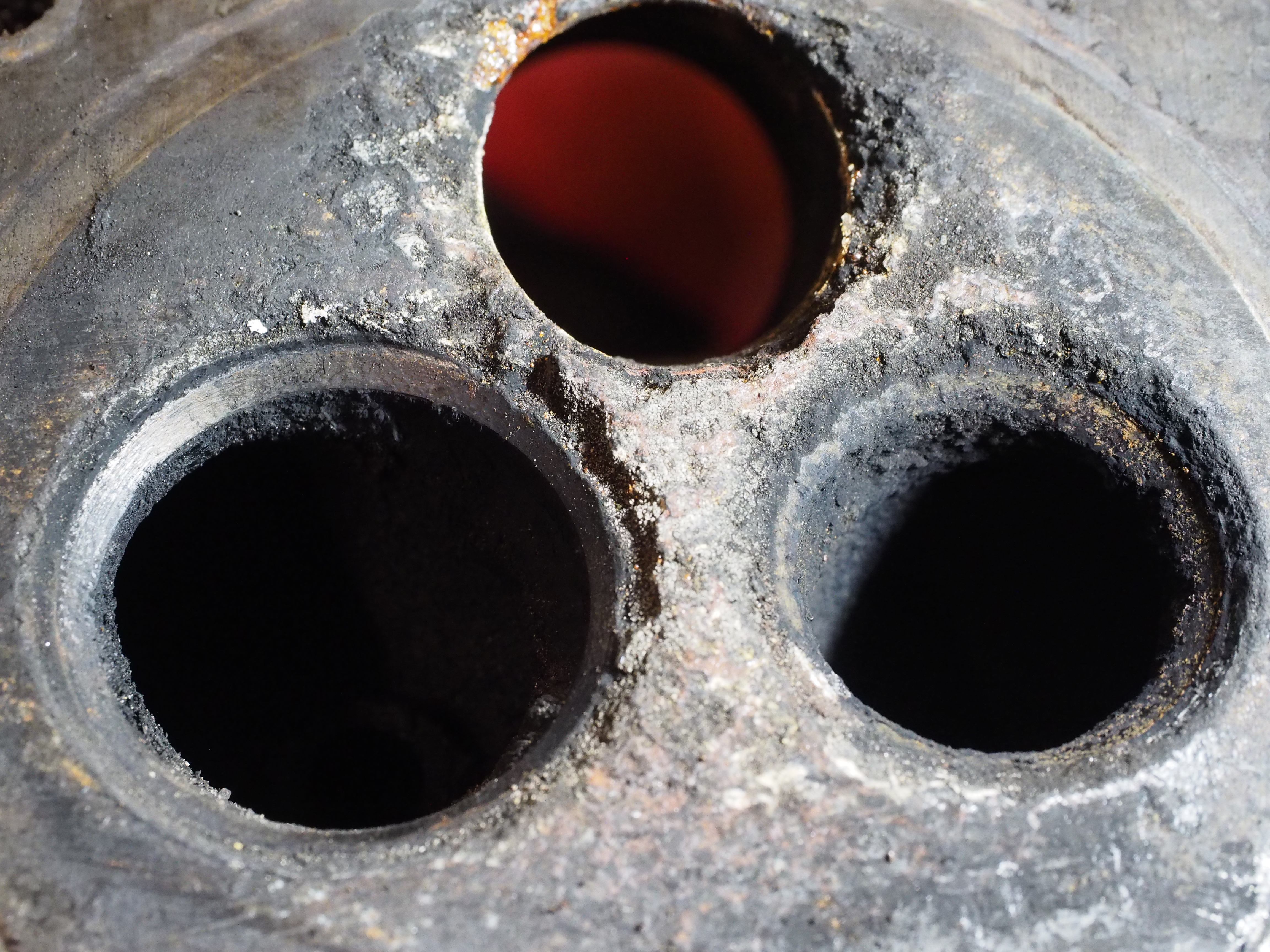
If the pre-combustion chamber isn’t to be removed at a later stage then it will be necessary to clean the face where the injector seats as it is normally covered in carbon. This picture shows what the bottom should look like after cleaning – initially it will typically have carbon deposits that may stop an injector seating correctly.
Injector assessment and overhaul isn’t covered here as there is a separate Technical Tip on that.
Cylinder Head Removal
With the rockershaft removed, removal of the cylinder head is normally simply a case of removing the bolts. It is usually a good idea to release each half a turn in the reverse order to which the cylinder head is torqued down to minimise any risk of warping the head. The IH head is quite robust so isn’t likely to be a problem, but better safe than sorry. If you don’t know the recommended order, heads are usually tightened down in a circular patter spiralling out from the centre, so this time they are loosened slightly spiralling inwards.
This unit however introduced a twist as one of the bolts sheared off in the block.
This bolt had been inserted without its washer and was dry and rusted into place. It should have been oiled when inserted. Also there was debris in the bottom of the hole so it had locked up at the bottom too. The centre of the bolt was drilled and the hole eased out till the helicoil threads were visible, but everything was still rusted solid. The helicoil had also become rusted in place so it too proved difficult to remove before it could be replaced. All because the previous person didn’t oil the threads as per the workshop manual.
Cleaning and Inspection of Head Face
The face of the cylinder head that mates with the head gasket usually has debris stuck to it and rust in the area where water couples between the block and the head. I find the easiest way to clean this and similar cast iron faces is an angle grinder with a wire brush attachment. Provided that one isn’t heavy handed this is quick and effective for removing rust, carbon and even the most resistant of thermostat housing gaskets.
I’ve never had one of these cylinder heads warp, but this would be a good time to check it for flatness with a straight edge. A backlit simple 12” steel ruler should be quite accurate enough for this task.
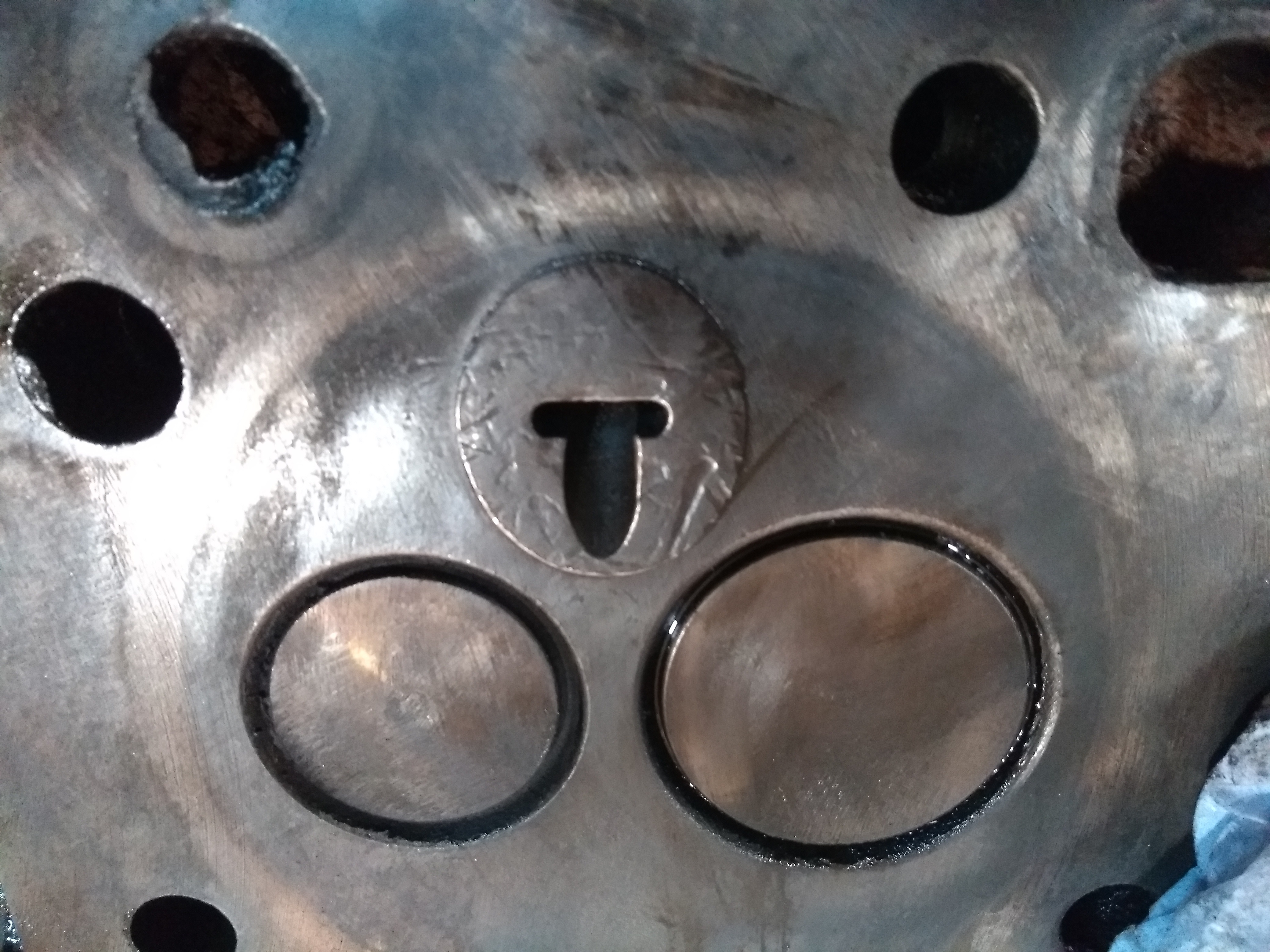
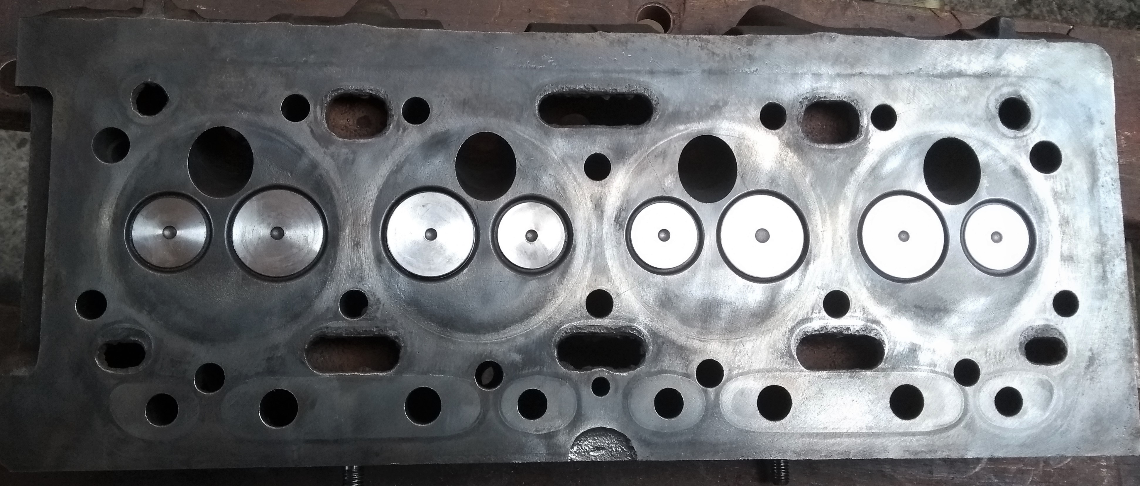
The head needs careful checking for damage, especially around the valve seats and the pre-combustion chamber.
This picture is of another engine that was run with a leaking head gasket for a while. The area around valve seats and pre-combustion chamber were badly eroded so a new head was needed. Anglo part A58959 was used as a replacement and it comes with new valves, guides and springs etc. My replacement head included pre-combustion chambers but I understand this isn’t always the case – it depends on the manufacturer. If you replaced the head you may wish to check if the pre-combustion chambers are included.
Sometimes there can be a crack between the valve seats.
The pre-combustion chambers can sometimes crack – any sign of damage in this area could lead to parts of the pre-combustion chamber falling into the cylinder so, if in doubt, swap them.
On my engine all these areas were ok but there were marks in a couple of the pre-combustion chambers. As I had a spare set it was decided to swap them, but if they’re ok then there is no need to disturb them.
As an aside, Anglo’s pre-combustion chamber (A67390) include its two brass sealing washers.
Pre-Combustion Chamber Removal
The workshop manual describes a quite complex tool for removal and yet another tool for alignment of the new part, but I’ve found them not to be needed. The only time such tools would be necessary would be to remove the pre-combustion chamber with the cylinder head still in place, not a common event.
Carbon build-up holds the chambers in place – I don’t know if the damage in the photograph was down to someone removing the part with a screwdriver, but my solution is a socket and copper mallet.
Because the pre-combustion chamber is in a circular hole angled to the face of the cylinder head, then its face (which should be parallel and almost flush with the head) is elliptical. I use a socket with a diameter slightly less than the minor diameter of the ellipse, line it up carefully and, with a sharp tap from the mallet, the carbon build-up should break. Use a smaller diameter socket once it starts to move, taking care not to damage the edges of the hole as they become exposed.
This picture shows the four pre-combustion chambers mounted (actually stuck) on the injector spacers.
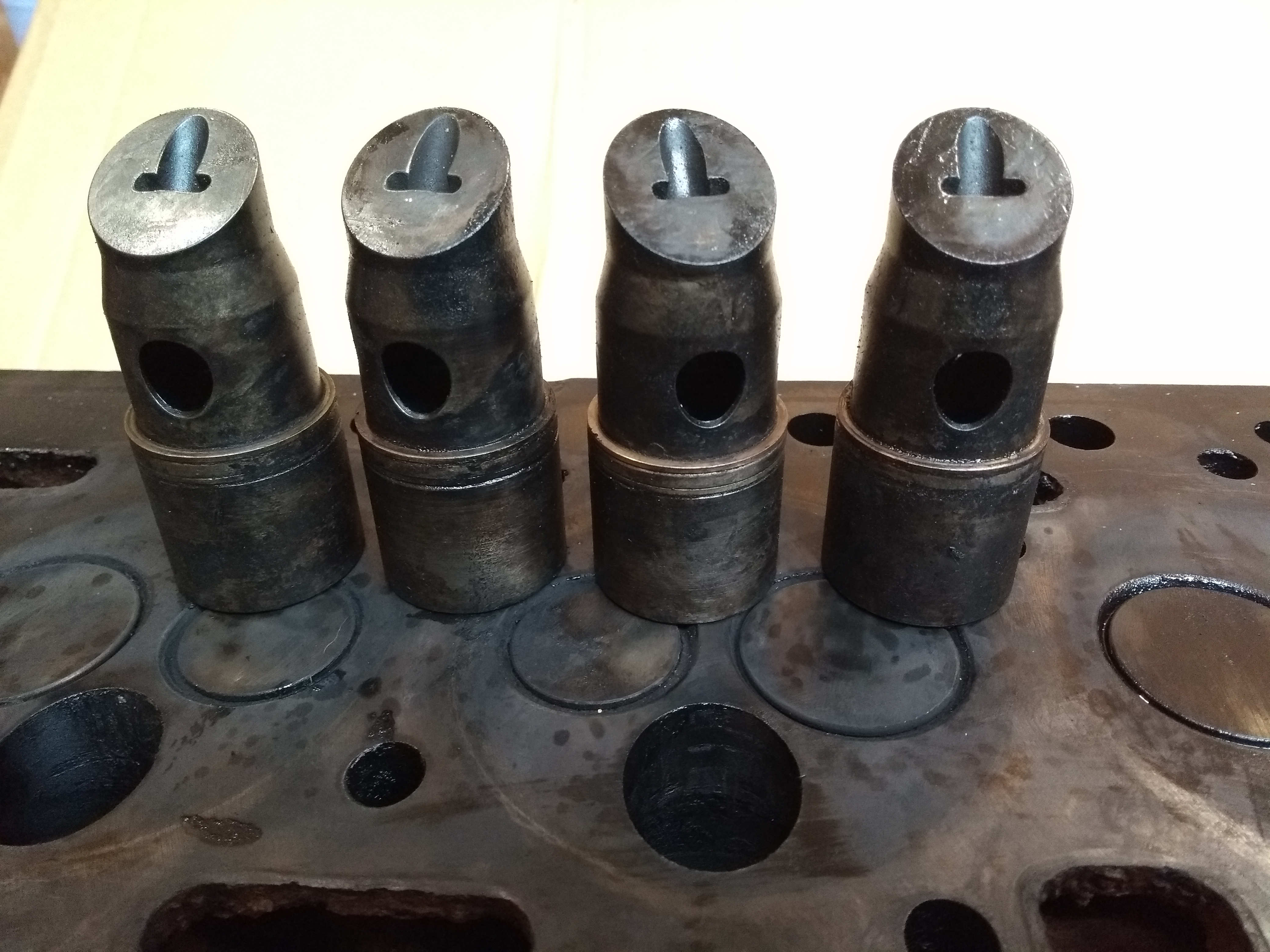
These are a simple loose push fit but with carbon build-up are normally difficult to separate. I’ve found that holding and rotating the pre-combustion chamber while repeatedly tapping the spacer with a copper mallet gradually separates the two parts. DO NOT USE A HAMMER as the spacer will be damaged and not refit correctly.
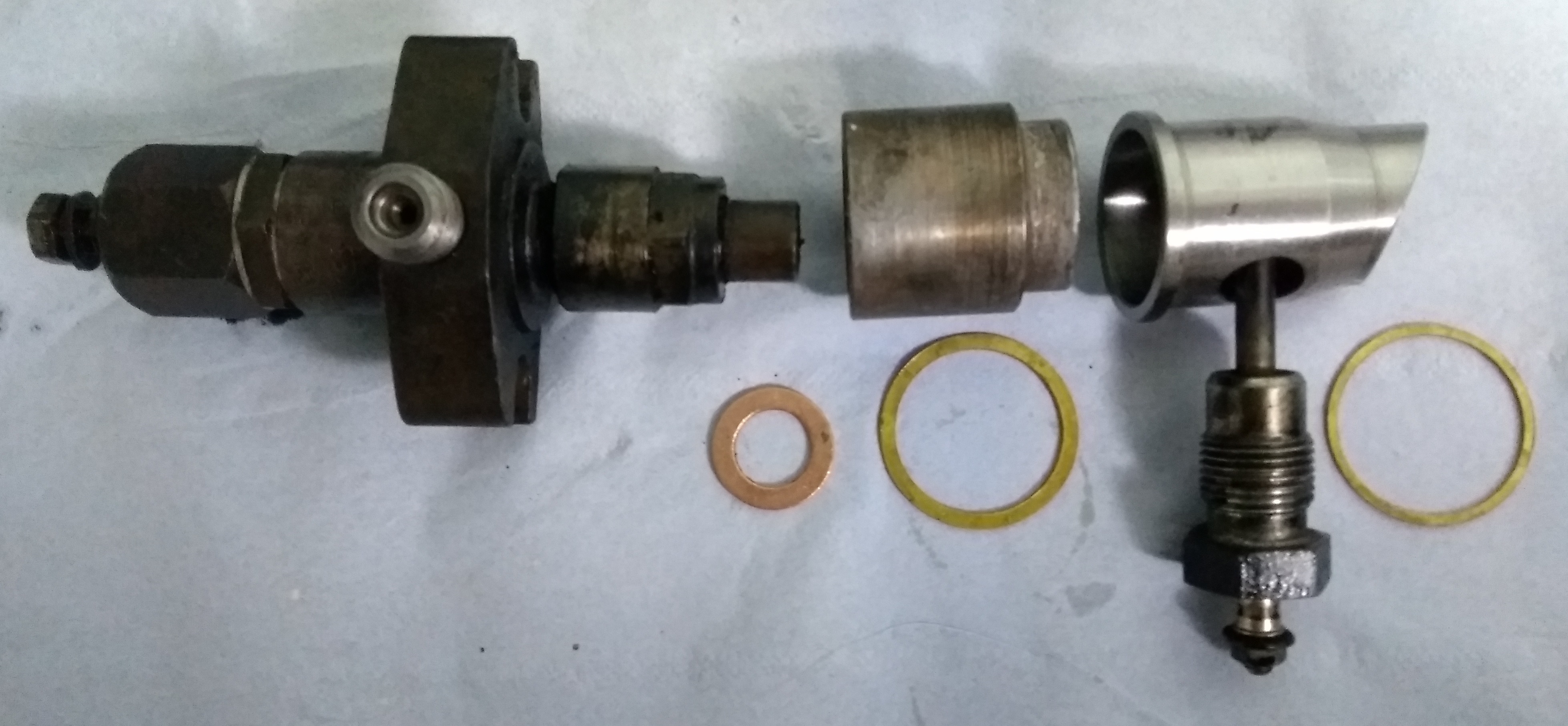
This picture shows the order that the various parts fit together. Working from left to right
- The injector has a copper washer which provides a seal between injector and spacer
- A brass washer seals between the spacer and the pre-combustion chamber
- The glowplug (in this case on of the 12V versions) is shown where it will eventually fit inti the side of the pre-combustion chamber
- The final brass washer seals between the pre-combustion chamber and the cylinder head.
Interestingly, even though only one part number is listed for the pre-combustion chamber holder for all the BD144 and BD154 engines that I’ve researched, a B275 that I rebuilt had these two different versions. Three extra washers had been added to make it the same length. I rebuilt the engine with four of the type to the right of the picture (and the same as shown in the earlier picture), but with a single washer.
Even such a small change as this improves the compression ratio as the volume at top-dead-centre is primarily determined by the pre-combustion chamber. Sliding the holder further into the pre-combustion chamber made a noticeable improvement to starting.
Removal of Valves
I’ve a couple of different valve spring compressors. This is a Bergen tool and is rather flimsy (the arms spring apart under tension) and is on the small side when it comes to reassembly. It could work better if I changed the right spacer (which presses on the valve head) with a shorter pad.
When removing the springs (double springs on the BD154 engines, single on the BD144), once the tool starts to bend, give it a tap with a copper mallet on the spring side to release the collets. It should then compress the springs easily.
This picture shows the springs, cap, bottom spring support and collets from a BD154 engine.
The BD144 engine only has a single outer spring… unless the cylinder head has been replaced with the later BD154 version.
The valves can now be removed and inspected, along with their seats in the cylinder head. Keep the valves in order should you wish to reuse them.
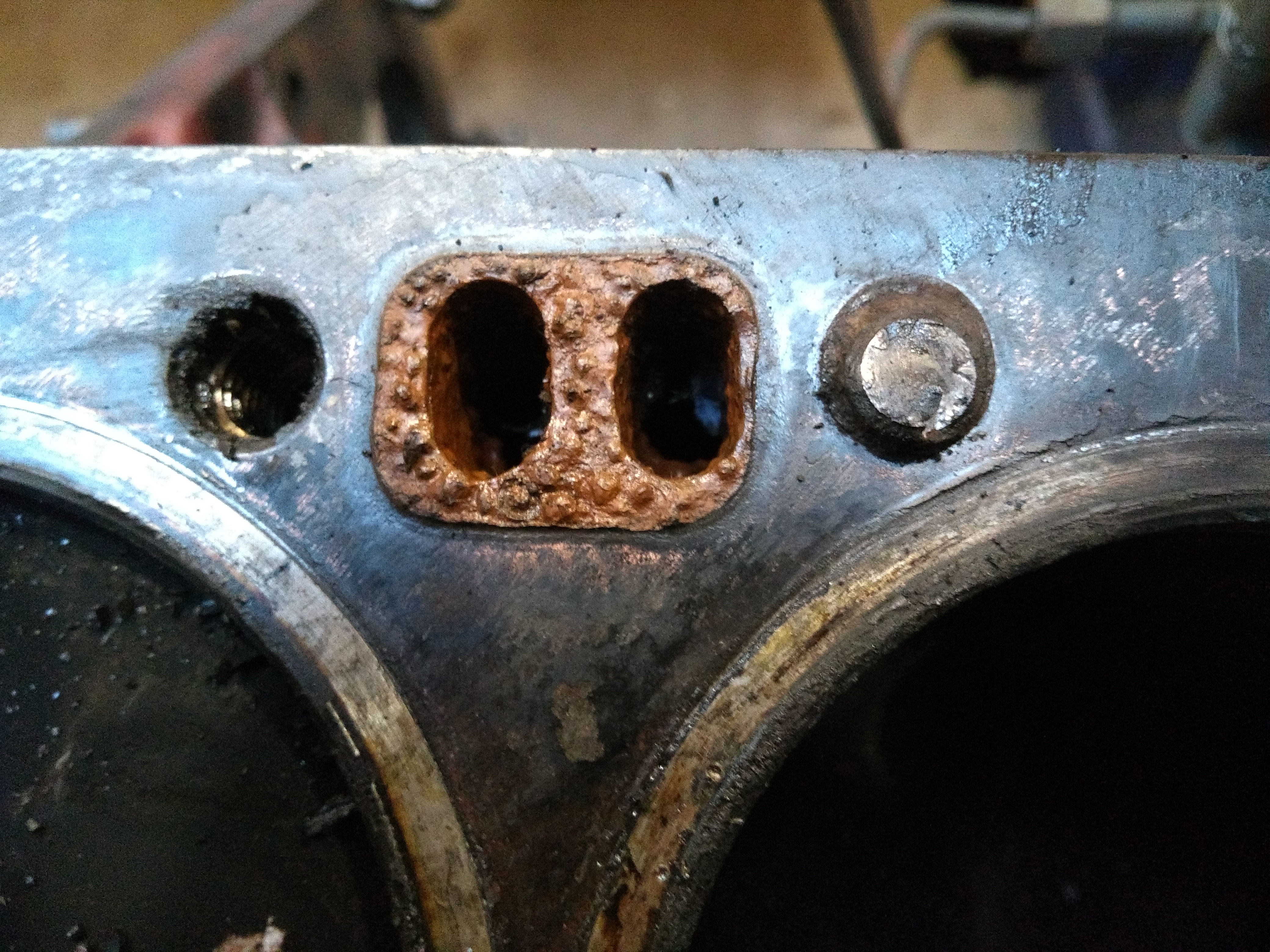
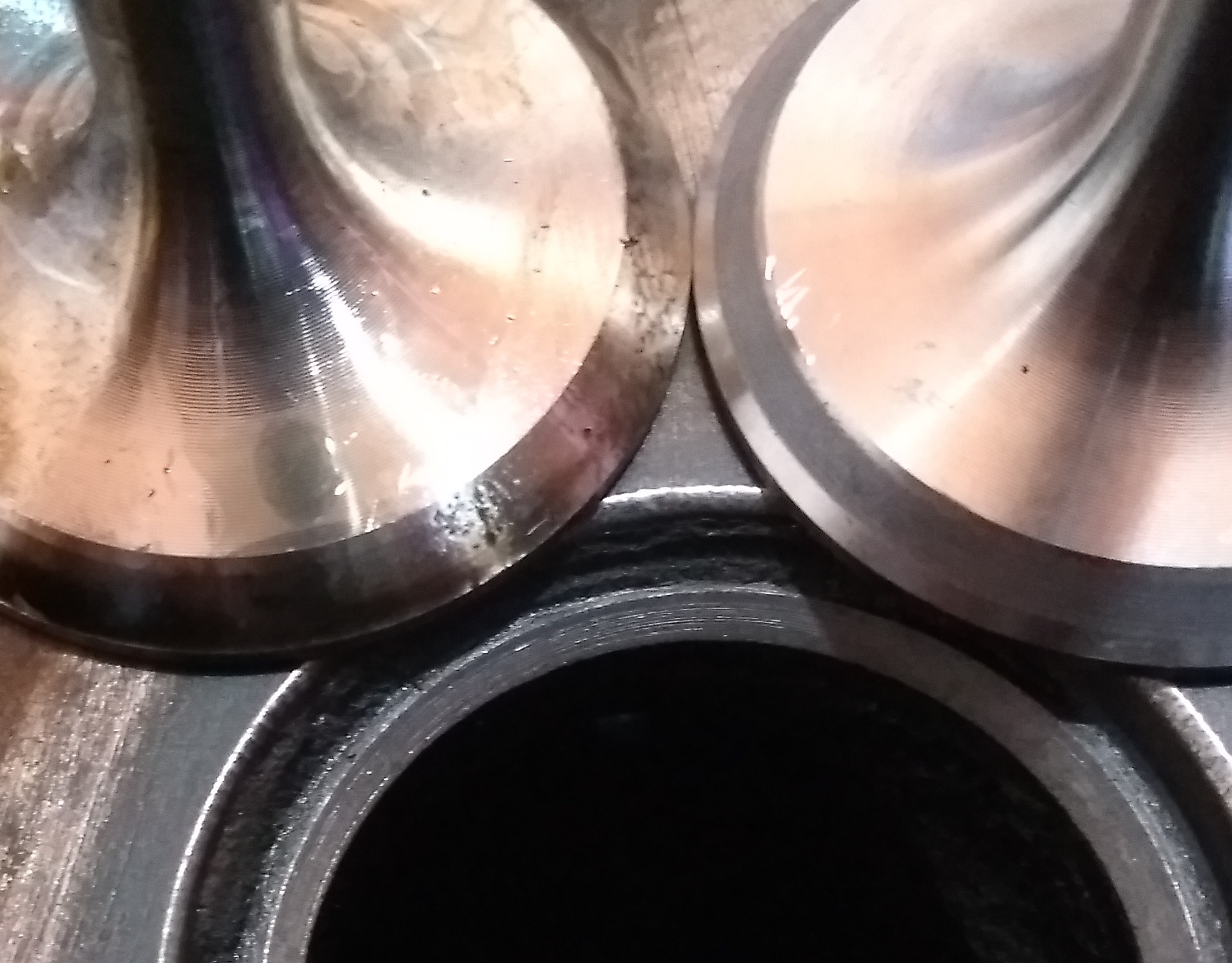
This picture shows
- The hole left by the pre-combustion chamber (top)
- Inlet (left) and
- Exhaust (right) valve seats.
In the bottom of the hole the valve guides are just visible.
The inlet valve seats were in good condition but the exhaust valve seats show a little pitting and needed re-cutting before grinding back in.
Checking Valve Guide Clearance
Clean all valves and the inside of the guides. With the valve lubricated with engine oil it should move up and down smoothly and without any binding. The procedure below will allow precise measurement of clearance but generally, if you can feel ANY sideways movement the valve and/or guide are worn.
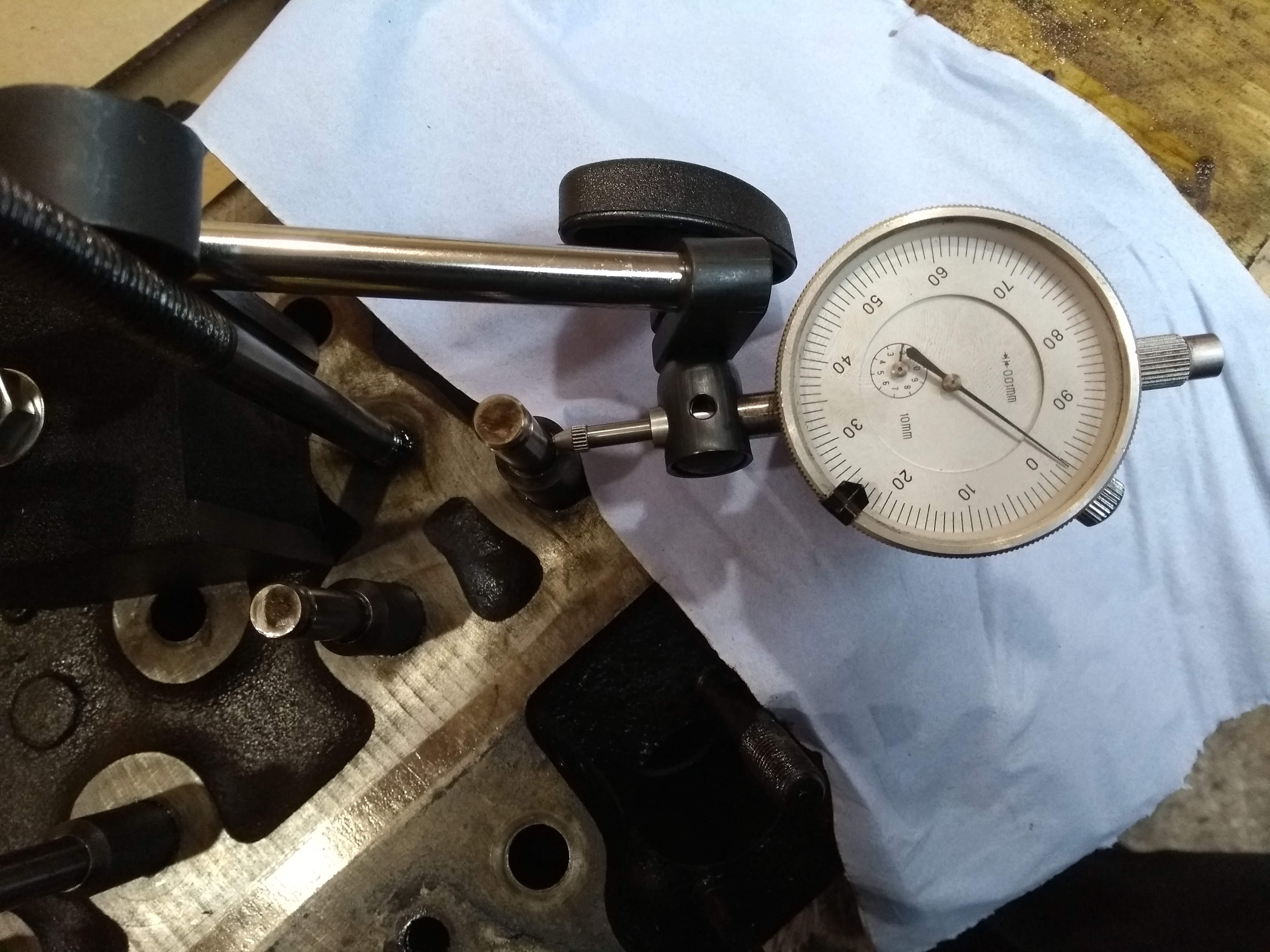
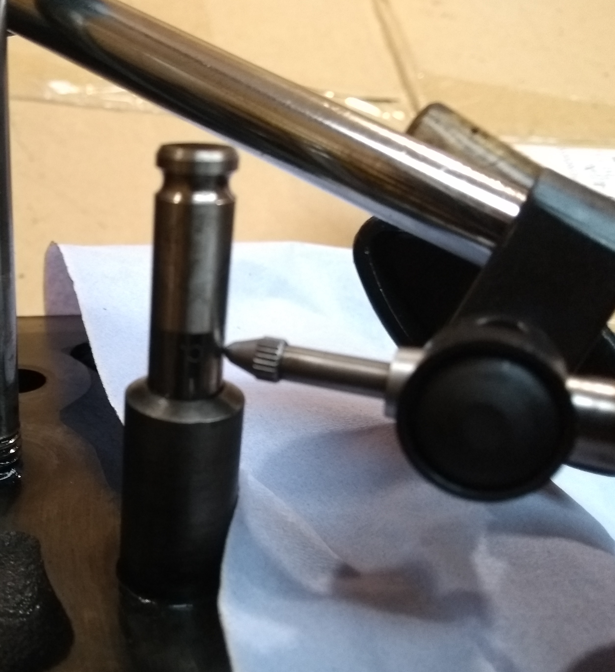
Valve guide clearance can be checked quite easily with a dial gauge on a magnetic stand as shown in these two photographs.
Set the gauge so it rests against the valve stem close to the top of the valve guide.
Move the valve stem from side to side while noting the gauge deflection.
Repeat this for all 8 valves.
The workshop manual specifies clearance as 2-4 thou (approximately 0.05 to 0.1mm).
On this engine two were just on the top limit while the others ranged from 5 to 13 thou… and one of the valves had the top of its stem bent, presumably with careless assembly when the engine was last rebuilt as wear marks were visible on its side.
The inlet ports were covered in oil and the worst exhaust port was partially choked with heavy carbon build-up.
During an inlet stroke, the inlet port is at lower pressure than atmospheric, so oil is drawn down the loose guide into the inlet port. This provides one reason for increased oil consumption.
During the exhaust stroke, the exhaust port is at much higher pressure than atmospheric. A worn guide here will blow exhaust gasses into the rocker box and out of the breather. This also provides one explanation for this engine’s heavy breathing.
This engine seems to have done little work since its last rebuild as the liners show little wear but, because the state of the valves and guides was ignored, several problems were left that could have been fixed relatively easily.
Changing the Valve Guides
To change the guides one needs access to a press – I found my small 6 tonne press to be adequate for the task and convenient to work with on the bench.
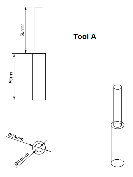
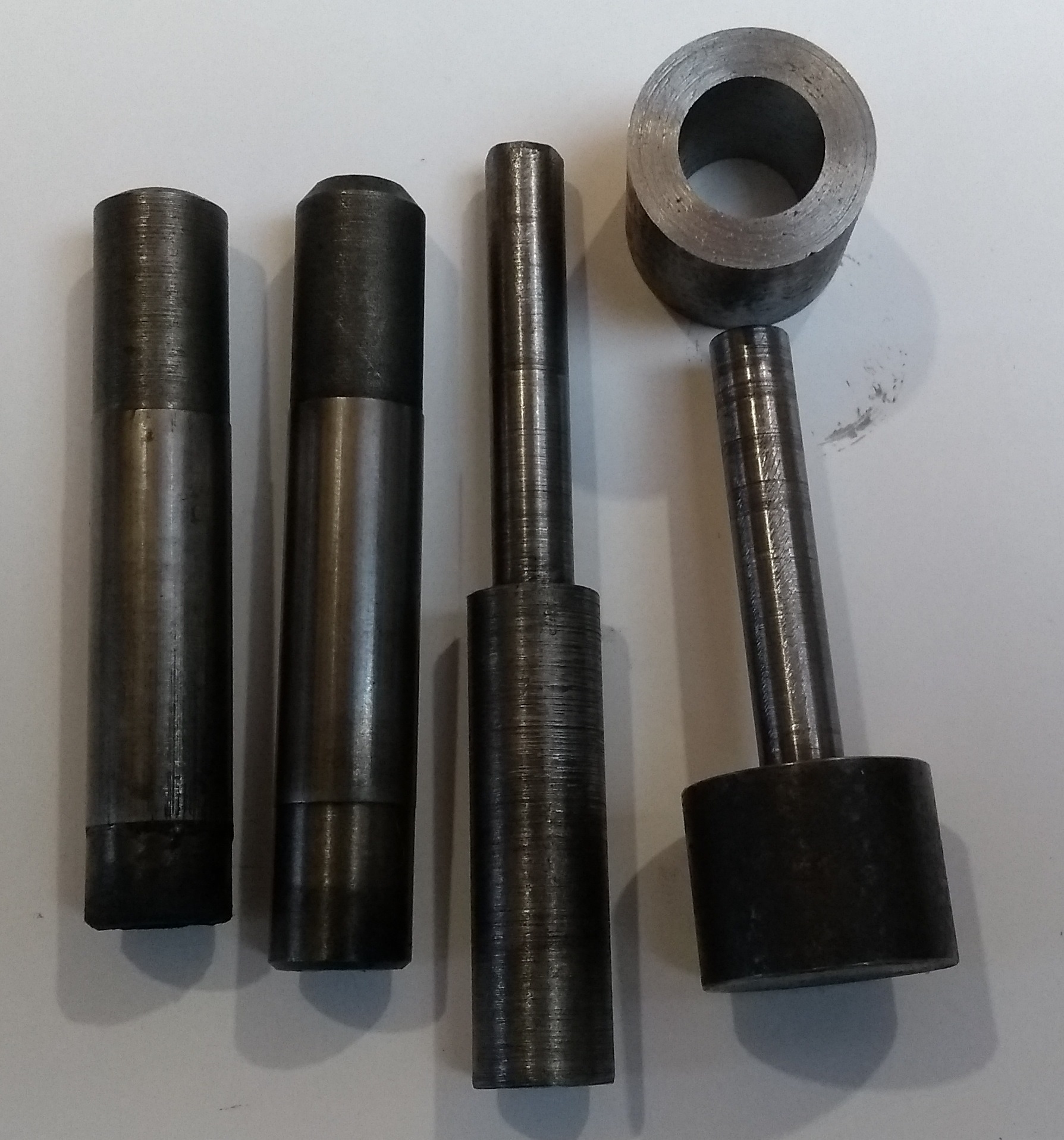
I turned up 3 special tools on the lathe. There are other ways to do the job but these make it easy.
The first tool (Tool A) is designed to fit into the valve guide. It fits inside the guide to keep it aligned and just clears the hole in the cylinder head as the guide is pressed out.
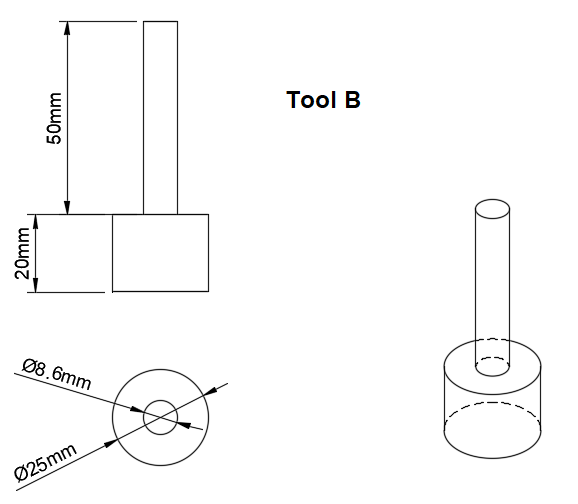
The second tool (Tool B) is used to press the guide into the cylinder head. The thin section fits into the guide to keep everything aligned while the larger diameter bears onto the guide to push it into place.
The final tool (Tool C) just makes life much easier. The guides are pressed in but must stand proud of the cylinder head by a fixed amount. This tool fits as a spacer outside the guide as it is pressed in and limits how far tool B can push in the guide. Inlet and exhaust guides have the same projection so one tool makes this setting easy.
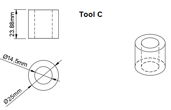
The actual projection is listed as 0.940” +/- 0.030”. Tool C length shown here is 0.940” in metric.
When I inserted the guides they all projected by about 0.010” greater than the nominal (possibly my machining wasn’t that accurate!) but were still well within tolerance.
This picture shows the old guides and the three tools.
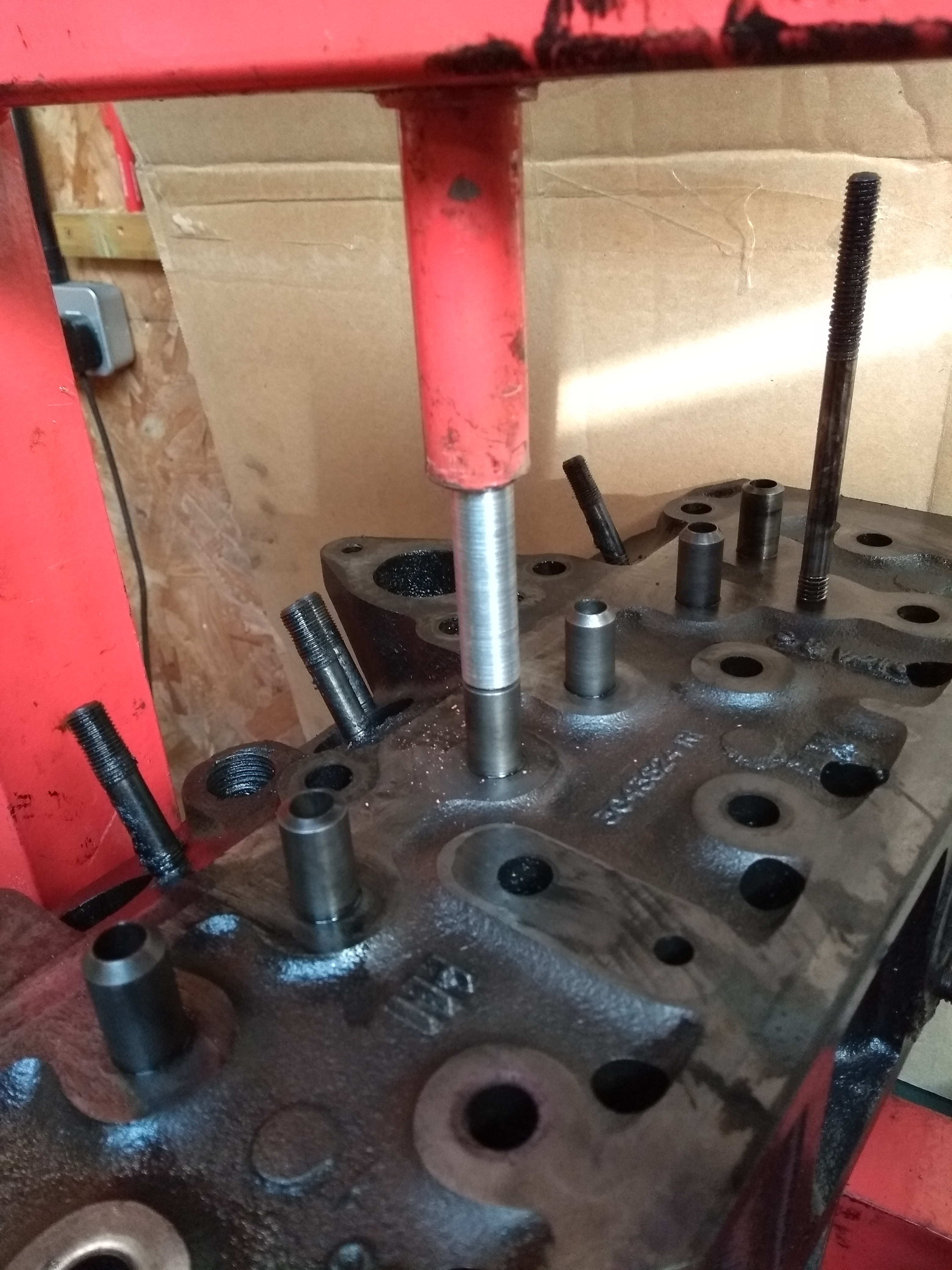
With the tool, pressing out the old guides is a simple task. The main difficulty is supporting the cylinder head level as it is moved under the press.
Take note of which way up the guides fit as there is a right and wrong way round. Also inlet and exhaust guides aren’t the same length.
Inserting the new guides is also quite simple with these tools.
Inlet (Anglo part A66045) and exhaust (Anglo part A60213) guides are different lengths – the exhaust guide is the shorter one.
To make insertion easier the guides could have been in the freezer for a while but I found they would press in ok when at the same temperature as the cylinder head.
It will help to coat the new guide in oil before trying to press it in.
I positioned the guides in the correct order and gave them a gentle tap with a copper mallet to start them into the holes and ensure they were properly aligned before using the press.
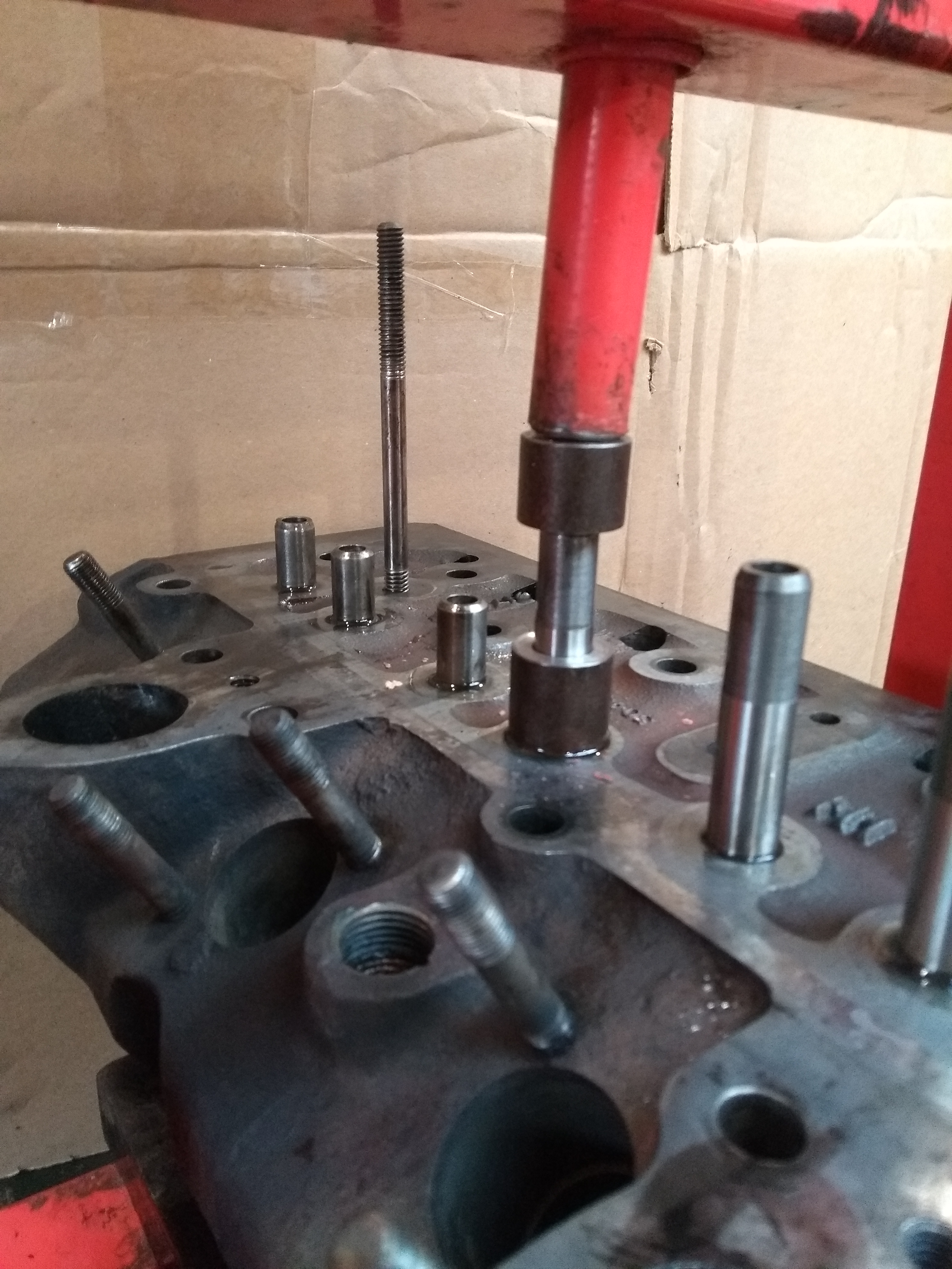
This photograph was taken before any pressure was applied – the cylinder head needed final adjustment to ensure that everything was in alignment vertically before applying pressure… and that needed the hand that was holding the camera!
One final step once the guides are inserted is to check that the valves move smoothly. The valve stems were oiled and tried in the appropriate guide in turn. 7 were ok but one was rather tight and so it needed careful easing with an expanding reamer, so this may be needed. Do not try to get away with a tight valve as it may seize in use and hit the piston.
Re-cutting Valve Seats
The old advice used to be that when changing valve guides it was necessary to re-cut the valve seats to ensure concentricity. With increased accuracy of modern machining I haven’t normally found this to be necessary but, as mentioned earlier, the exhaust valve seats needed some attention.
I’ve found these seats to be very hard and the valve seat cutter that I’ve had for 50 years wouldn’t touch them. I’d bought a set of carbide cutters from India but unfortunately it didn’t include an 11/32” pilot so I had to make one from an old valve stem. NOTE the cheaper carbon steel cutters will not cut these seats; it has to be carbide tipped types.
In the past I used a local engineering company to change a single guide and recut the seats. This cost significantly more than buying a complete new cylinder head from Anglo… and the seats weren’t that well cut either. So, unless you expect to rebuild several engines, if the seats need re-cutting then a replacement head may be quicker, easier and cheaper.
Grinding-in the Valves
I’ve used the same type of grinding paste for 50 years - Anglo sells it (A67332). The tin is double-ended with coarse and fine paste at the top and bottom – start with coarse and finish with fine.Only apply a thin layer on the valve head, lifting the valve clear from time to time to clean the surfaces and re-apply.
TAKE GREAT CARE NOT TO GET THE PASTE IN THE VALVE GUIDE.
I usually use methylated spirit for cleaning as I progress as it is important to see how things are going.

To rotate the valve the classic tool is a grinding stick like this (Anglo A67334) and it is normally used by rolling it between two hands. This is hard work!
I’ve had one of these for years but take the rubber suction cup off one end and mount it in my battery drill. There are various other tools available online.

This photograph shows a new inlet valve (left), one that has been lapped (right) and the corresponding valve seat (below.)
The aim of lapping is to achieve a continuous matt finish in an unbroken ring on both the valve and seat as can be seen here.
And finally the cylinder head is ready for the pre-combustion chambers and injectors to be fitted.
Fitting Pre-combustion Chambers & Injectors
The pre-combustion chamber, two brass washers and the holder are assembled as in this photograph.
Ensure that the hole in the cylinder head where this fits is clean then slide everything into the head. Make certain that the end of the pre-combustion chamber is correctly aligned with the head’s face then insert the injector with a new copper washer.
NOTE If the pre-combustion chamber isn’t at the correct angle, one side will be standing proud of the cylinder head when it is fully inserted… if so it will need removing and realigning so its front face is parallel to the cylinder head face.
If old washers should have to be re-used, anneal them by heating to cherry red and letting cool in air.
Double check that the pre-combustion chamber hasn’t rotated, then tighten the injector securing nuts to the correct torque (20 – 30 ft-lb.) There should be a washer between each nut and the injector. The nuts should screw onto the oiled studs using finger pressure only before final tightening – if they are too stiff then the torque setting will be meaningless and the three washers fail to seal.
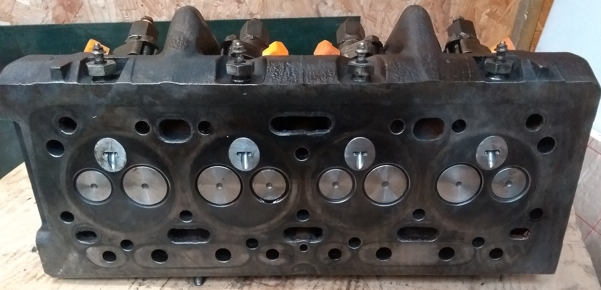
This is with the pre-combustion chambers, injectors and glowplugs installed. These glowplugs are the 12V versions with only a single connection to each.
This is the top view of the completed cylinder head. To protect the injector fuel and leak-down connections from contamination, I made protective caps and sleeves on my 3D printer. I’ve used tape in the past but thought it time to put my new toy to use.
The cylinder head is now ready for reassembly on the engine.
The next part of this series will address the timing gears and camshaft, the probable cause for the rattle described in Part 1.
ARTICLE CONTRIBUTED BY ANDREW CHAPMAN
© ANDREW CHAPMAN & ANGLO AGRIPARTS LTD


Licence Terms
You are free to: Share, copy & redistribute the material in original format for any purpose as long as you follow the license terms below:
- Attribution – you must give appropriate credit and provide a link to the original article in a reasonable and visible manner
- You may not in any way suggest that the licensor endorses you or your use.
- No Derivatives – The material must be distributed in full, including disclaimer, you may not distribute or share modified material.
- No additional restrictions – You may not apply legal terms that legally restrict others from doing anything the licence permits.
- No warranties are given. The license may not give you all of the permissions necessary for your intended use. For example other rights such as publicity, privacy, or moral rights may limit how you use the material.
Disclaimer

Related Articles

International Harvester 434 Major Works Part 1 – Initial Strip-down
Contributor Andrew Chapman undertakes a major overhaul of his International Harvester 434. Part 1 is discusses the initial strip down of the tractor in preparation of the work.

Ferguson TED20 - Cylinder Head Rebuild Part 1 - Video Tutorial
First in a series about rebuilding the cylinder head on our Ferguson TED20. In this video we show you how to; check the head and engine block surfaces, install the valve guides and lap the valves.

Ferguson TED20 - Cylinder Head Rebuild Part 2 - Video Tutorial
Ferguson TED20 - Cylinder Head Part 2 - Video Tutorial. 'As we saw in the last video the valve guides need reaming. Using a new set of adjustable reamers we just bought, in this video we have a go at getting this job done.'

Ferguson TED20 - Cylinder Head Rebuild Part 3 - Video Tutorial
Lapping the valves was not giving us a great result so we decided to buy a valve cutting set and freshen the valve seats.
-200x200.png "International Harvester 434 Major Works Part 3 - The Oil Filter That Didn't")
International Harvester 434 Major Works Part 3 - The Oil Filter That Didn't
An oil filter is meant to filter oil and this engine didn’t filter oil at all. Read Andrew Chapman's article as he investigates the issue with his BD154 engine on an International Harvester 434.

International Harvester 434 Major Works Part 4 - Strip, Clean & Initial Inspection
In Andrew's latest article he focusses on the stripping, cleaning and initial inspection of the various components fitted to the engine block on his International Harvester 434.