
International Harvester Bradford Built Tractor Brakes
WARNING - Old brake linings may contain asbestos. Great care should be taken not to inhale any dust and use brake cleaner to damp down and remove any found.
Introduction
The Bradford built International Harvester tractors span a model range including the 250, 275, 414, 434, 276, 354, 444, 374, 384 and their industrial equivalents.
The industrial versions had additional drum brakes fitted but that is not covered in this article.
The early tractors had one design of brakes while the later models had an improved version which approximately doubled the braking force. Upgrading from early to later brakes would require the whole rear end of the tractors (at least axles, transmission/differential housing and brakes) to be changed so is not really a practical option.
With the possible exception of a few bolts and the expander ball bearings there are no parts common between early and later brakes. Be careful when buying spares as many suppliers wrongly imply that the same parts fit all tractors.
Most of these tractors now have poor or non-existent brakes, the tractors suffering bent nose cones and pierced radiators as a consequence. Fixing the brakes in most cases is relatively simple with the exception of leaking differential half-shaft seals, something that is covered in a subsequent article.
Identification
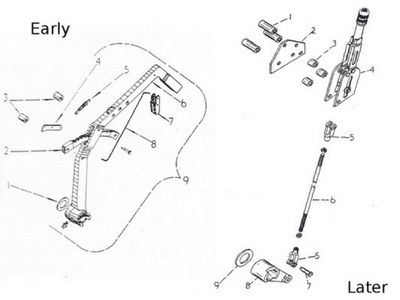 The early brakes were fitted to B250 plus B275 and B414 models built before about 1963/4. Generally the early brakes also used a ratchet handbrake while the later models used an over centre (either on or off) mechanism.
Both types of brakes used twin double sided friction disks operating on the differential half-shafts. A pinion on these shafts is then coupled via a large gear to further reduce the speed but allow braking on a faster rotating shaft.
The early brakes were fitted to B250 plus B275 and B414 models built before about 1963/4. Generally the early brakes also used a ratchet handbrake while the later models used an over centre (either on or off) mechanism.
Both types of brakes used twin double sided friction disks operating on the differential half-shafts. A pinion on these shafts is then coupled via a large gear to further reduce the speed but allow braking on a faster rotating shaft.
Between the friction disks is what IH calls the actuating disk assembly which consist of two metal friction surfaces on disks separated by large ball bearings in teardrop shaped holes. This assembly is stopped rotating by the brake housing casting but, as the brake is applied, one half rotates against the other with the ball bearings moving up the teardrop holes and expanding the assembly to apply braking forces.
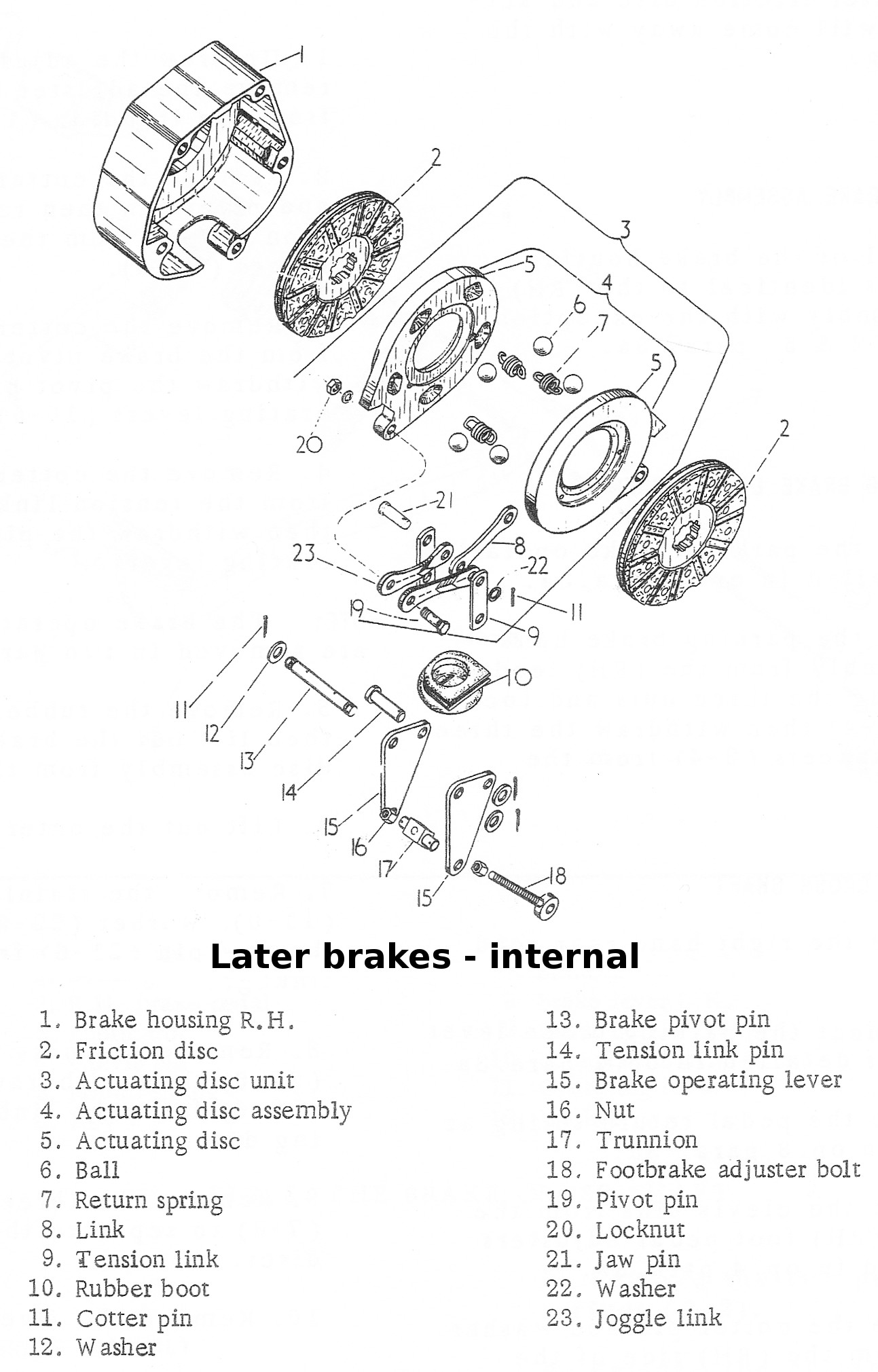
The early brake housing is held in place by 5 bolts while the later has only 4.
The early brake housing has a circular rubber sealing boot with a single hole for the actuator through its centre. The later brakes have a ‘D’ shaped rubber boot with two slits in it for the twin plates of the actuator.
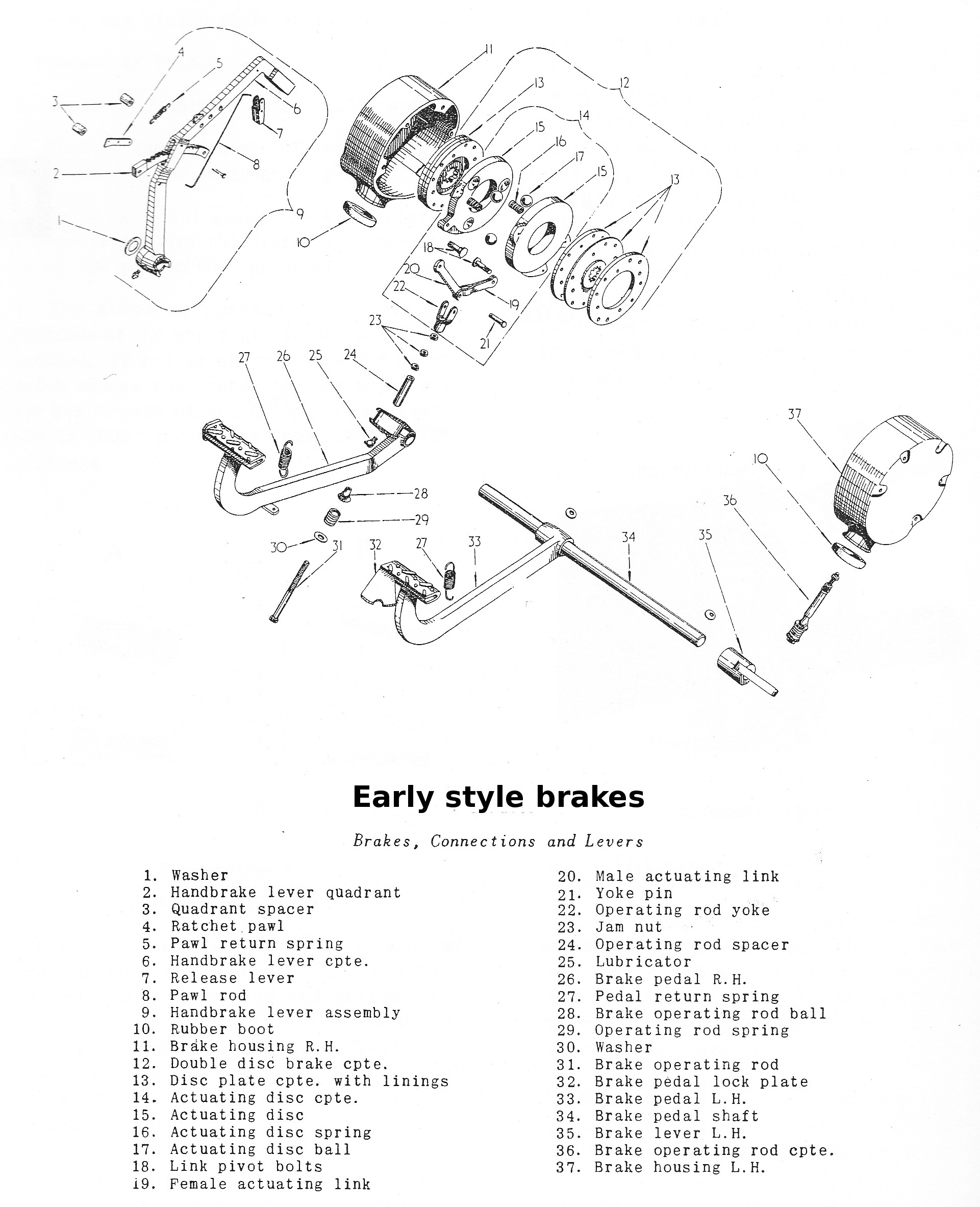
Early Brakes
 Early brakes used 5 ½” diameter brake disks, three ball bearings and three round ended retaining springs in the actuating disk assembly. The rubber boot dust seal is circular with a single hole. The brake pedal return spring is short – approximately 10 cm long.
The later brakes used a completely different handbrake arrangement from the early ratchet type.
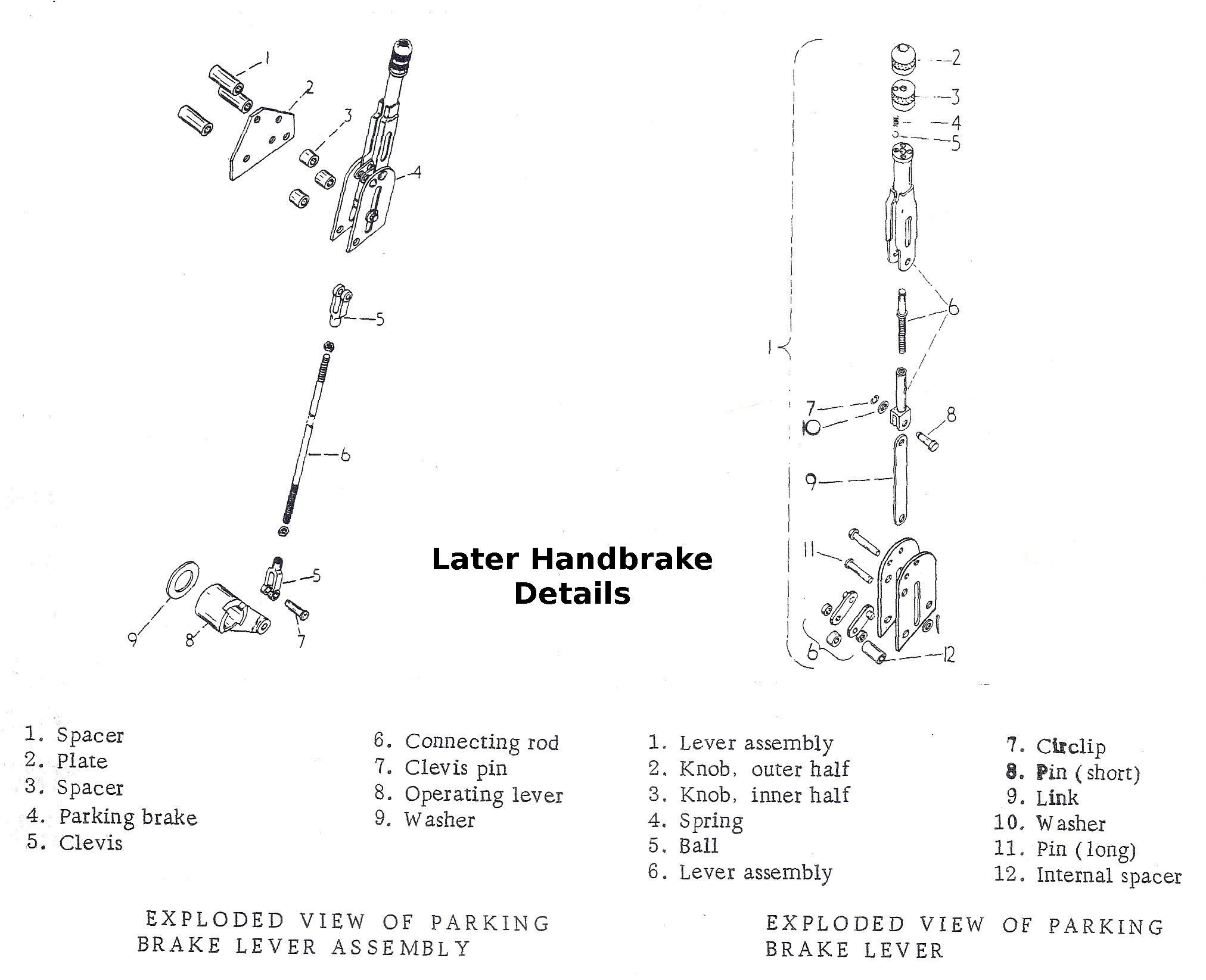
Later brakes used 6 ½” disks, five ball bearings between the actuator disks, flat topped springs and a “D” shaped rubber boot with two slits. The brake housing is held in place by 4 bolts rather than 5 on the early brakes.
With increased friction area and larger diameter (hence greater braking torque), the later brakes provide approximately double the stopping force of the early brakes.

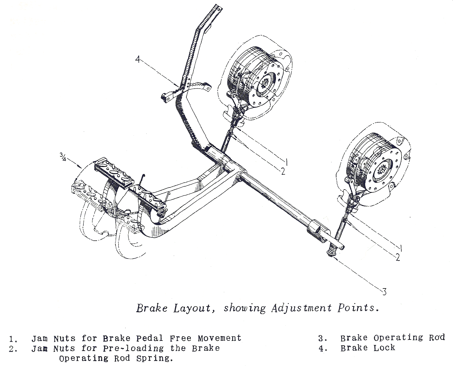
Adjustment
Early Brakes
This diagram provides an overview of the early brake mechanism.
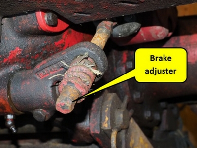
Adjustment is via the brake operating rod (item 3 in the diagram) and as shown in the photograph below.
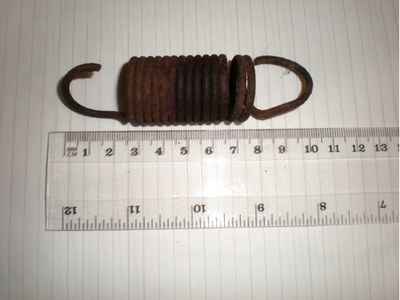
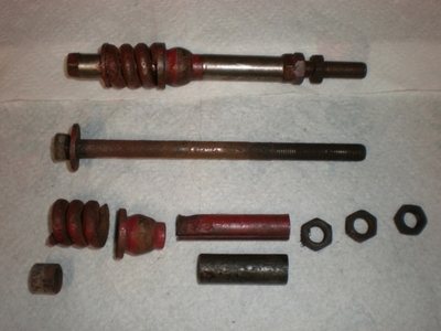 A heavy spring (often rusted solid) provides a degree of equalising brake pressure though in reality is generally ineffective and not part of the later brakes. The spring becomes shorter over time and no replacement is available so sometimes it is necessary to adjust the length of the spacer tubes as shown at the bottom of the photograph. Do however make sure that the friction material isn’t worn down too far – friction material is relatively cheap and easy to replace but not so the castings if they become scored by rivet heads.
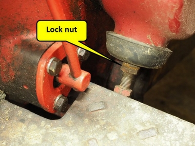 The jam/lock nuts on the brake operating rod are released and the rod screwed in to reduce pedal movement or out until the pedal free movement is ¾” then the jam nut tightened. Repeat for the other side and carefully road test to ensure that the tractor isn’t pulling to one side. If it pulls to one side, slacken the rod on the side to which it pulls then retest. Take care not to reduce the free movement too much or the brakes can lock on when hot
Later Brakes
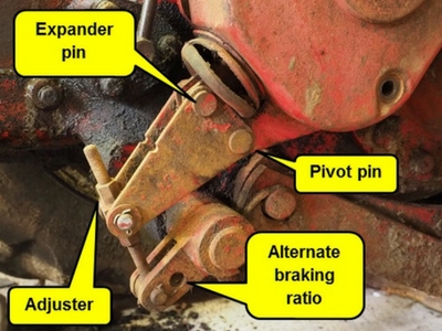
The later brakes have a different linkage with two arms in place of the rod and spring on the early brakes.
The adjuster has nuts above and below. As with the early brakes, screw down to take up slack and if the brakes pull to one side when road testing, slacken off on the side to which the tractor pulls. Again, don’t tighten too much or the brakes can lock on when hot.
Most tractors use the configuration as shown in the photograph but a second hole in the lower arm provides an alternate braking ratio giving lower braking effort traded off for increased pedal movement. If the brakes are working correctly however the normal ratio works well and is noticeably better than the early brakes.
General Dismantling
It is possible to dismantle the brakes with the wings (fenders) and footplates in place… but it generally much easier if they are removed. As a minimum it is usually necessary to disconnect the wing from the footplate, remove the front bolt holding it to the axle and, with the rear bolt loose, swinging it out of the way.
Some types of front loaders have their rear support mounted on the back axle and may need to be removed before the brake housings will come off. Similarly some types of cabs may have features which block access to the brake housings. Both of these “features” probably contributed to brakes on tractors never being maintained. Unfortunately getting access to the brakes may, on a 50 year old tractor, prove more of a problem than actually repairing the brakes but is necessary.
Removal of Diff-lock Pedal
Removal of the right hand housing is slightly more complicated in that the diff-lock pedal must be removed first. To do so, remove the two retaining bolt plus the pedal pivot bolt, taking care to note the position of all washers.
Some tractors have a spring at the back of the pedal to hold it up but it seems this was discontinued on all tractors after the B275 except for export models – as a consequence many tractors without the spring have a hole worn into the face of the pedal where it acts on the diff-lock making the pedal difficult to operate. It is therefore worth checking when the pedal is removed and filling the any hole if necessary.
With the pedal removed, removal of the right housing is the same as for the left.
Removal of Brake Housing
Removal of the brake housings are essentially the same for
both early and later brakes. Differences will be explained later but removal
consist of:
- On the right side, remove the diff-lock pedal –
details above
- Disconnect the brake linkage to the pedal – this
is different for each type
- Remove 4 (later) or 5 (early) bolts holding on
the housing and the housing lifts off with some or all of the contents
included… depending on what is wrong inside.
When removing the earlier brakes, simply slacken the
adjuster lock nut and unscrew the adjuster completely.
For the later brakes, disconnecting the linkage is more
complex. One can undo the adjuster to nut completely (usually the simplest
solution but the adjuster may be rusted solid and/or bent) or remove the bottom
pin on the adjuster arm or disconnect the expander and pivot pins plus removing
the split pins where the adjuster pivots in the triangular plate. The
triangular plates have notches in the top edge. Exactly what is removed tends
to depend on what has rusted solid over the years but everything will
eventually need splitting to free everything before re-assembly. The split pins
are often so badly rusted that it can be easiest to cut then off, file them
flush with the clevis pins (so the triangular plate can be removed) then punch
or drill out the remains on the bench.
With both types of brakes the outer friction disk and actuating disk assembly normally come off with the housing. The inner friction disk tends to stay on the differential half-shaft.
Inspection
These photographs are of the later brakes but the earlier version is very similar, including the drain hole mentioned later.
Differential half-shaft bearing housing
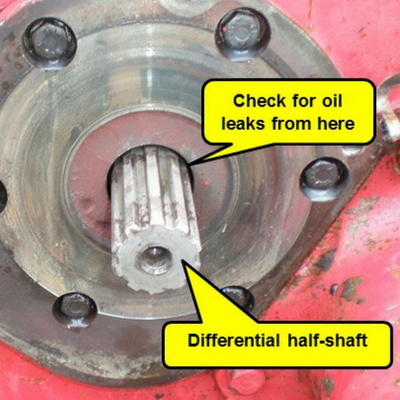
With the housing disks and actuator removed, carefully check for any sign of oil leakage from the differential half-shaft seal in the inner casting. If there is ANY sign of oil then the seals on both sides must be changed. This is a complex process and covered in a subsequent article.
This photograph shows the left brake with housing, actuator and friction disks removed. This face is actually part of the differential half-shaft bearing housing.
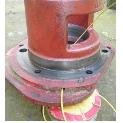
In the lower edge of this casting (the inboard friction surface of the brake) is an approximately 5mm diameter drain hole that is intended to drain any oil should there be a leak in the seal. This hole is regularly blocked with dirt over the years but it is very important to locate it and ensure that it is clear.
The yellow wire in this shows the hole which will only be visible when looked at from under the tractor… and even then is difficult to find.
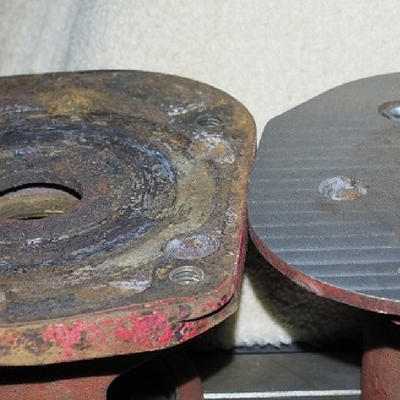
This photograph is of a pair of later type differential half-shaft bearing housings removed from a B414. The one on the left shows the original condition of both while the one on the right is after 60 thou had been machined from the surface to restore it to “as new”. The surface on the left would never have been able to provide safe braking but removal and skimming is not a minor task!.
Brake housing inner face
The inner face of the brake housing should also be checked – if it is as bad as the previous photograph then it will also need machining or a good second hand part sourced.
Brake actuator
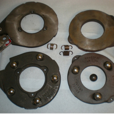
The later (left) and early (right) actuators are shown in this photograph. The top and bottom plates are mirror images of each other and, when assembled, have friction surfaces on the outside and the inner faces held apart by the ball bearings. The actuators are held in the brake housing in a way to stop them rotating. When the brake pedal is pressed the two plates rotate slightly relative to each other as the ball bearings roll up the teardrop shaped holes and force the plates apart. Expansion of the assembly forces the brake disks into contact with the actuator outer faces, the face of the differential half-shaft bearing housing and the brake housing inner face.
So, to get this to work correctly, everything should be clean, the balls rust-free, the springs unbroken (typically they are not under significant pressure when off the tractor) and the outer friction faces should be smooth and rust free. At the time of writing the early actuators are not available… but it is sometimes possible to take a light skim off their surface. Anglo Agriparts sell replacements for the later actuators. Springs and ball bearings are available – the ball bearings are actually all 7/8” diameter and are also available at reasonable prices from online bearing suppliers in a choice of materials suitable for this, e.g. stainless or chrome steel.
Replacement actuators are typically painted and/or covered in grease or oil. The paint from the friction faces and any grease or oil should be removed. When re-assembling after cleaning it is easy to get the two disks back to front. The holes for the springs should be in line with each other. If they are not then rotate the top disk and try again – don’t force the springs if the plates aren’t correctly aligned as they will be over stretched and useless. The actuators are assembled dry, i.e. without any grease or oil that could cause dust to stop smooth operation.
Brake pads
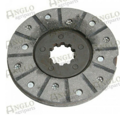
The early and later pads differ in diameter but are otherwise essentially the same. Replacement disks (complete with linings) or linings on their own are available for both the early (5 ½”) and later (6 ½”) disks.
Check that the disks are free from oil and grease, that there is plenty of friction material above the rivets and that the rivets are tight. If the surface has worn unevenly or is glazed, it is false economy to do other than replace them.
The disks should slide freely on the differential half-shafts without binding so ensure that the half-shaft is free from rust and burrs.
Rubber Boot
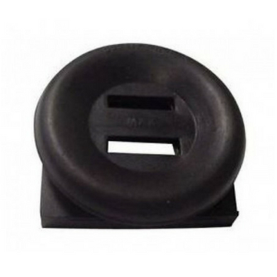
The rubber boot should always be in good condition. It keeps dirt and water out of the brakes, either of which will quickly damage critical surfaces and lead to a much more complex and expensive repair.
This photograph is of the later type of boot which is available from several suppliers. The earlier type is circular with a single circular hole. If restoring the earlier brakes then asking around some of the more specialist suppliers should provide a source.
Rebuilding
As they say, “rebuild is the reverse of disassembly”, but it is rarely as easy as that! The inner friction disk can easily be fitted to the differential half-shaft splines then the second friction disk and expander inserted into the housing. Getting the housing and its contents however to line up with the splines however can be quite difficult and may require some practice. The right housing must also align with the diff-lock shaft which fits through the seal in the housing, something that can at times make the task even more frustrating, especially with the early brake housing design.
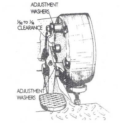
When reassembling the diff-lock pedal ensure that it is free on its pivot bolt and that its clearance is as indicated on the earlier diff-lock pedal diagram.
Once the housings are bolted in place, fit the rubber sealing bolt then the actuating rod. Adjust as described in the previous Adjustment section.
ARTICLE CONTRIBUTED BY ANDREW CHAPMAN
© ANDREW CHAPMAN & ANGLO AGRIPARTS LTD
PART 2: BRADFORD BUILT BRAKES - MAJOR OVERHAUL


Licence Terms
You are free to: Share, copy & redistribute the material in original format for any purpose as long as you follow the license terms below:
- Attribution – you must give appropriate credit and provide a link to the original article in a reasonable and visible manner
- You may not in any way suggest that the licensor endorses you or your use.
- No Derivatives – The material must be distributed in full, including disclaimer, you may not distribute or share modified material.
- No additional restrictions – You may not apply legal terms that legally restrict others from doing anything the licence permits.
- No warranties are given. The license may not give you all of the permissions necessary for you intended use. For example other rights such as publicity, privacy, or moral rights may limit how you use the material.
Anglo Agriparts nor any such reviewers or contributors of content provides any warranty or guarantee as to the accuracy of any information on this website and cannot accept liability for any errors or omissions. The information in this article are for general information purposes only. It does not constitute legal, technical and/or commercial advice and should not be relied upon as such. Specific advice should always be sought separately. Despite the authors best efforts the information provided in this article may not be accurate, up to date or applicable to the circumstances of any particular case. Anglo Agriparts nor the author of this article make no representations or warranties of any kind regarding the completeness or accuracy of the information contained herein and accepts no liability for loss or damage whatsoever and howsoever arising from reliance on it, regardless of whether such information originates from Anglo Agriparts, or our contributors. Anglo Agriparts has no control over the content on any other website accessed through this website and accepts no liability for any loss or damage whatsoever and howsoever arising from reliance upon the content of such websites. Neither Anglo Agriparts nor any reviewer or contributor of content on the website shall be liable to any person for any loss or damage which may arise from the use of the information contained in this article or on this website. These exclusions of liability will not apply to damages arising from death or personal injury caused by the negligence of Anglo Agriparts or any of its employees or agents or of a reviewer or contributor of content.


