
Bradford Built International Harvester Major Brake Overhaul
While there are several descriptions around on how to change the brake disks on the Bradford built International Harvester tractors, a full restoration is a quite different and major task.
This article should be read in conjunction with the earlier general article on these tractors’ brakes. This article concentrates primarily on the additional work necessary for the major overhaul.
There were two different type of brakes fitted to the Bradford built tractors. The B250 plus early B275 and B414 used a smaller 5 ½” disk while later models used the larger 6 ½” disks – the change probably occurred sometime around 1963/4.
It isn’t possible to upgrade without changing the whole rear end of the tractor and the spares aren’t interchangeable.
The following description is primarily for the later brakes as on this ’67 B434 but applies equally to any tractor fitted with the later brakes. Operations on the earlier brakes are very similar and subsequent notes will highlight any differences.
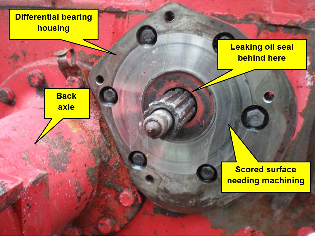
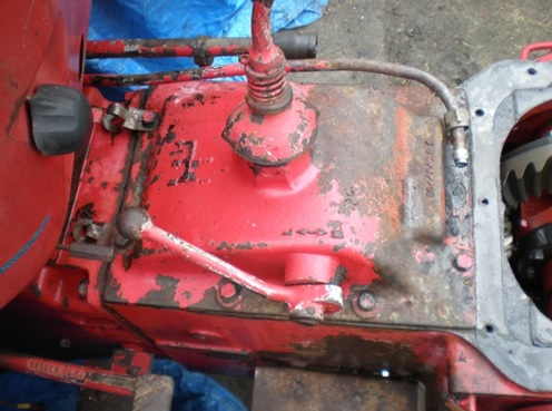
This tractor arrived with absolutely no braking, so the investigation started…
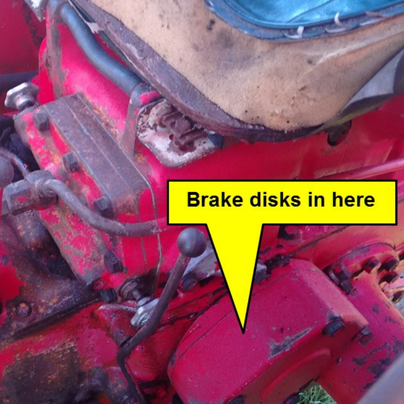
To begin, the cast cover shown above needs to be removed. The linkage between the brake pedal and brakes is different for the two sizes of brakes but disassembly is relatively obvious and explained in detail in the previous article.
The right side brake cover carries the diff-lock pedal which needs to be removed – take note of the position of the various spacer washers as when the pedal is replaced there should be a slight gap between it and the supporting bracket.
Four bolts (five for the early brakes) hold each cover in place. When the cover was removed, everything fell apart in a sticky oily mess. 5 of the 6 springs holding the expanders together were broken. The rivets on the disks were so worn that one disk only had a single rivet still holding the friction material to the central metal plate and, as a consequence, the friction surfaces were badly scored.
So just about everything that could be wrong, was! To fix, it needed:
1. Relined brake disks
2. Replacement expanders & springs
3. Replacing the oil seals
4. Re-facing the casting friction faces
5. New rubber sealing boots.
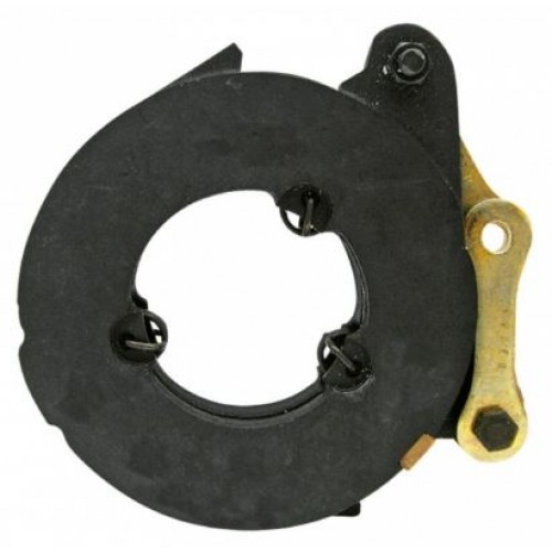
Inside this cover are two brake disks with friction surfaces on both sides like this and an expander.
The 6 ½” expanders have 5 ball bearings each and 3 flat-topped springs to hold the top plate to the bottom
The 5 ½” expanders use only 3 ball bearings and 3 round topped springs.
The two halves of the expanders are mirror images and fit one over the other with the balls held in place by the springs.
Purchase them here.
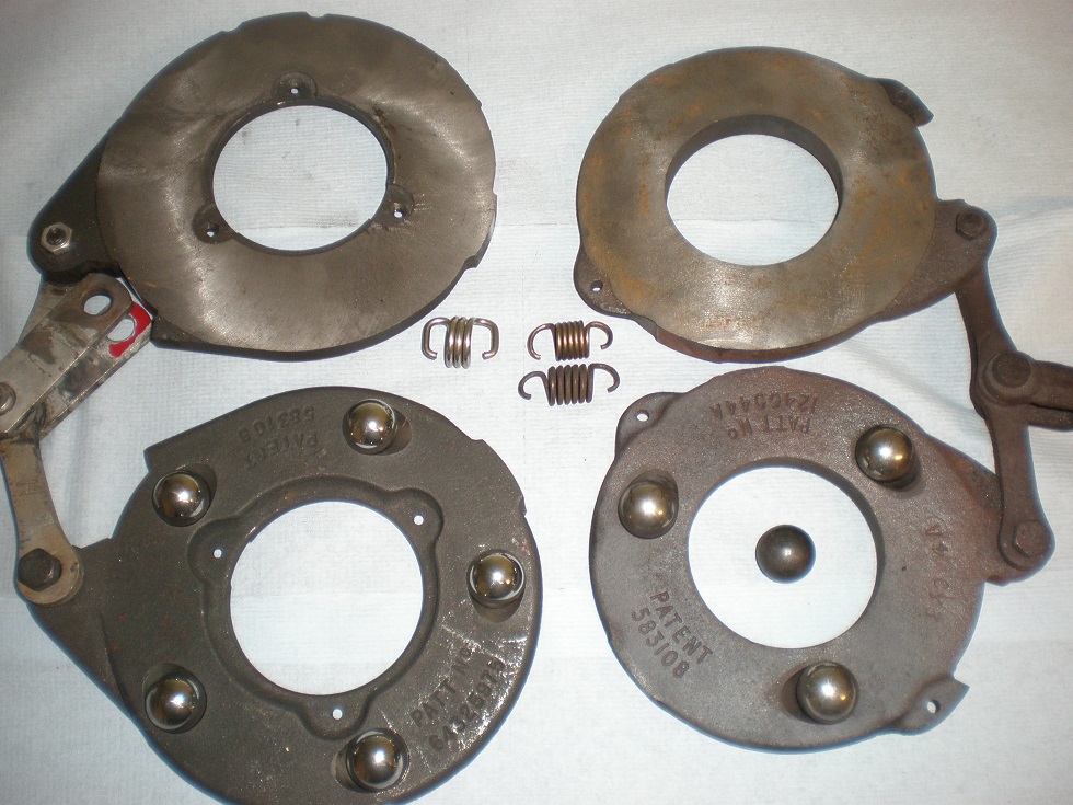
This photograph shows both later (left) and early (right) types of expander with ball bearings and example springs.
The brake pedal pulls the arms which cause the two castings to rotate relative to each other, forcing them apart as the balls roll along the teardrop holes. This in turn causes the rotating brake disk friction pads to press onto the four non-rotating surfaces (2 being the outside faces of the expander, 1 being the inside of the cast cover shown above and 1 being the face of the differential bearing housing described later.)
When the two castings are assembled their springs are roughly vertical – if this is not the case then the top casting needs to be rotated through 360 degrees as the linkage is reversed.
New expanders were obtained from Anglo Agriparts. These were good quality and well protected with grease and paint, but needed to be prepared before use. The paint on the outer friction faces was removed with a wire brush on an angle grinder then everything degreased. These expanders are normally installed dry with no grease on the ball bearings or inner surfaces.
Changing the Oil Seals and Re-facing the Inner Friction Face
Doing these tasks required the inner casting (which holds the differential bearings) to be removed… and that is a BIG job
This is where the restoration gets serious! At commercial rates, this is the sort of job that could cost well over £1,000 to change two £3 seals. It may have helped everyone if the design engineers had to try changing seals themselves!
First the cab had to come off. It hadn’t been off for 50 years and without heavy lifting gear was quite a task.
Then the rear wheels, wings and seat had to come off. The wings and cab were badly rusted so have been replaced with the alternative “shell” style wings which allows the tractor to be stored under cover.
The transmission oil needed to be drained. There are three square headed drain plugs to remove and about 18 litres of SAE 80/90 oil… unless water has been getting in around the gear lever when there could be more.
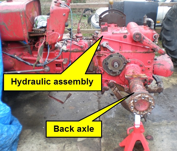
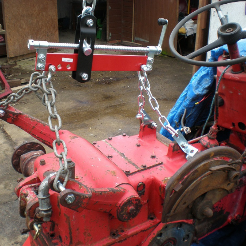
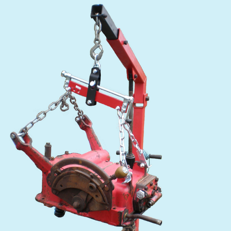
The engine hoist started to earn its keep as the hydraulics weighs about the same as a car engine. The hydraulic oil was drained before attempting to remove the hydraulic casting.
The casting initially resisted removal with the rear end of the tractor lifting off the axle stands. Changing the forces to lift front-back-front-back etc. eventually persuaded the joint to separate.
The early hydraulics have a bolt at the front under the valve/piston assembly and this can easily be overlooked. Both versions of hydraulics have dowel pins on either side so care is needed not to lift one end much more than the other as that could break the casting.
1. The left bull gear must be removed before the right one, so if only the right seal needs to be changed then the left side must also be dismantled.
2. The diff-lock shaft O-ring retainer and spring need to be removed before the right diff-lock half shaft will come out of the differential.
This process is described later but MUST be done before the right differential half shaft bearing housing is removed.
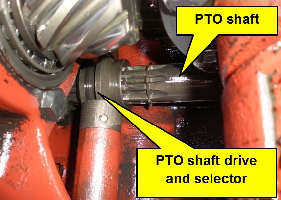
A sliding splined sleeve couples the PTO shaft to the gearbox. If the selector is in the wrong place when the PTO shaft is removed the clutch drops into the bottom of the casting and can be hard to refit. It is easiest to remove the PTO shaft with PTO engaged so the clutch stays on the driving shaft.
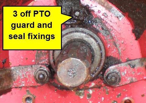
The PTO shaft pulls out the back after 3 bolts (or nuts on some tractors), which hold on both the PTO guard and seal housing, are removed.
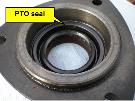
With the PTO seal housing out, it was also a good time to replace the seal.
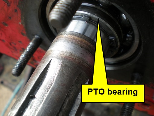
Sometimes the PTO shaft simply pulls out with its bearing, but on this tractor it needed a puller clamped to the PTO shaft to extract them both.
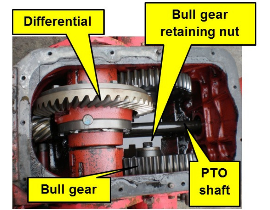
The bull gears fit on the splined back axle half shafts and are retained by a bolt which is normally torqued to somewhere in the 210 to 310 ft/lb region (different model tractors specify a large range of torque settings for this nut.).
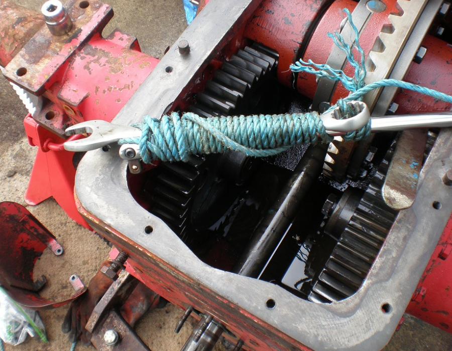
The thin walled socket used gave way (now replaced with a 6-point stronger version) but, as a short term solution it was Heath Robinson to the fore. This method of extending an open ended spanner (3 foot wrecking bar) can be surprisingly effective at times, provided that the spanner is of good quality.
The axles now were removed – again the engine hoist helps as these are awkward and weigh over 50kg each.
The photograph shows a view with the left axle removed and the differential half-shaft with the bearing housing around it. The bull gear is visible inside the hole left by the axle. The bull gears were then lifted out (left side first) followed by the 6 bolts holding each differential bearing housing.
As mentioned earlier, the diff-lock actuating shaft O-ring retainer must be removed before the right bearing housing will separate from the differential.
In the diagram opposite, items 1-5, the first spring 6 and item 7 are all retained within the differential assembly. The diagram doesn’t make clear that the spacer (item 3) is pushed against item 1 by the first spring (item 6) which is held in place by the collar (item 7) which is retained by the dowel pin (item 4.) This grouping of components is held within the differential gear assembly.
Shaft 5 passes through the differential half-shaft (the gear not numbered in the diagram) with the second spring (item 6), O-ring retainer (item 8) fitted to the outboard side of the differential half-shaft. The spring and O-ring retainer are held in place by a fine wire clip (item 12) – these three items need to be removed to allow the differential half-shaft (which is held between bearings in the bearing housing) to fully release from the differential.
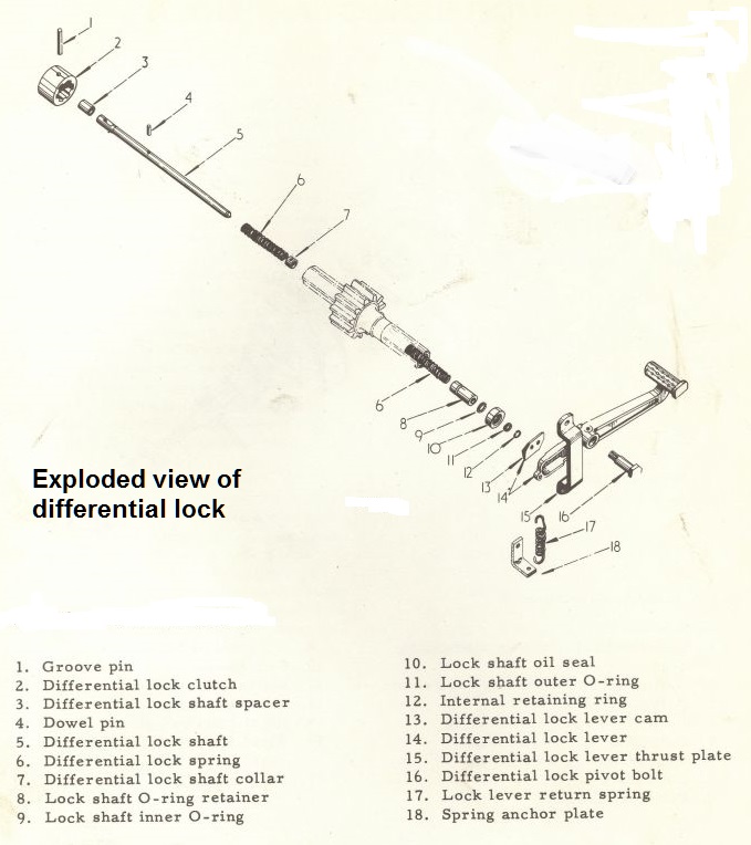
The wire retaining clip (item 12) is exposed by pushing in the O-ring retainer along the diff lock shaft… but there are complications. As the retainer is pushed in (e.g. with a screwdriver), the outer spring (item 6) compresses and the shaft also moves in unless it hits a stop of some form.
The only stop available is the diff lock clutch (item 2) which normally catches on the end of the left diff half-shaft… but it is possible for the clutch to engage and the O-ring retainer will not move on the shaft. If this happens, rotate one half-shaft against the other slightly and try again.
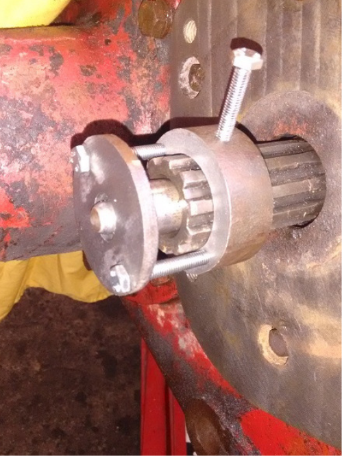
Even when the clutch doesn’t engage, the shaft moves in a significant distance as the inner spring (item 6) is compressed as the pin (item 1) moves along the slot in the shaft (item 5)… and the springs are quite strong. With the springs compressed, the wire clip (item 12) can be removed, possibly with the help of an assistant.
After doing this on a previous tractor, I made a compression tool to help both with the disassembly and reassembly of the O-ring retainer. The end disk is counter-bored to locate on the O-ring holder and is relatively thin in this area to make access to the retaining wire clip easier. The task is much simpler with this tool and less time is spent looking for the small wire clip as it shoots into dark recesses of the workshop.
The bearing housings were removed (along with the differential half-shafts) taking care not to damage the shims between them and the transmission casting, freeing the differential at the same time. This is a very good time to examine the diff-lock clutch which is visible inside the differential assembly.
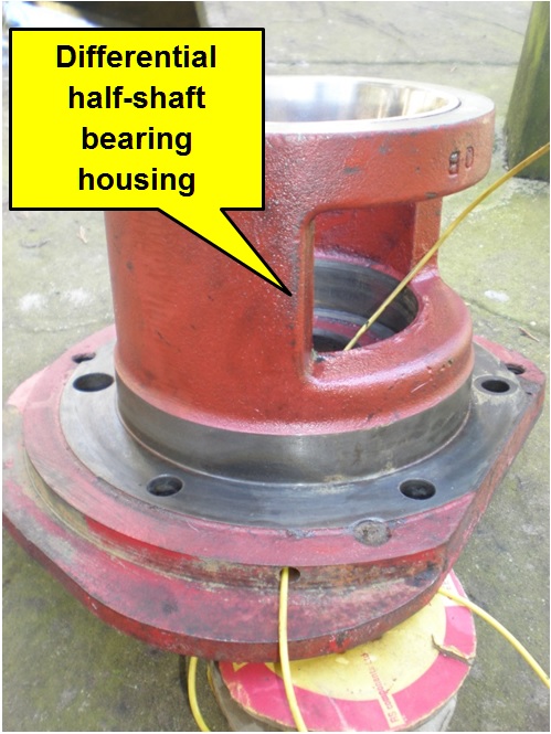
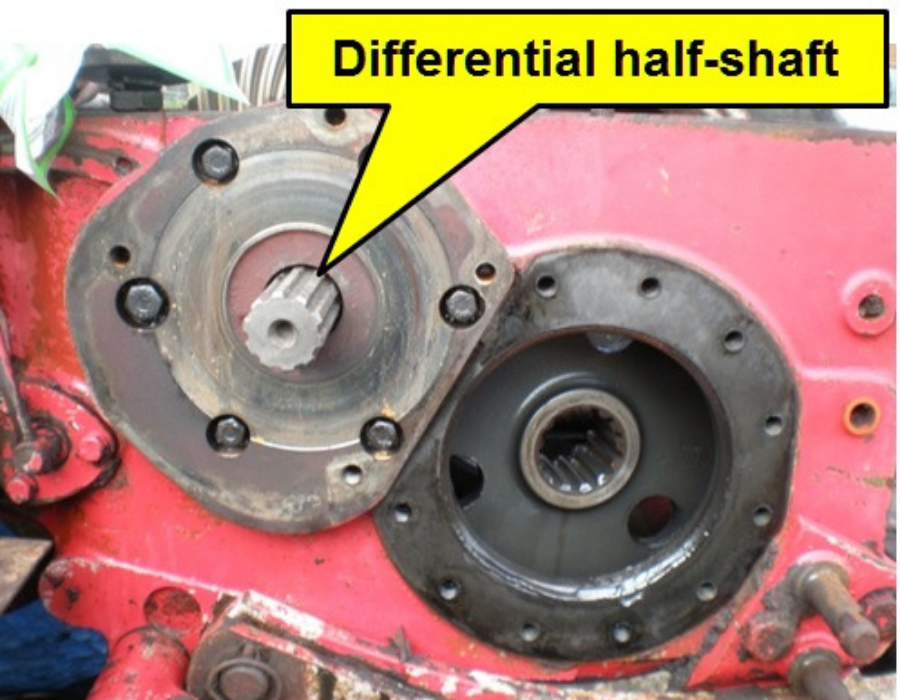
The differential half-shafts were pressed out of their bearings, the casting front face machined flat in the mill and, eventually, the oil seal replaced. This photograph shows one of the differential half-shaft bearing housings – the face that it is sitting on is the brake friction surface and the large hole to the side is where the bull gear engages with the half-shaft pinion.
The gap in the side is where the bull gear engages. The yellow wire indicates a hole intended to let oil from a leaking seal out rather than contaminate the brakes.
On this tractor the hole on each side were blocked solid – had they been clear then there would at least have been some braking. Most owners don’t know about these holes so they are filled with dirt and can’t do their job.
It is a sensible preventive maintenance task to identify these holes and ensure that they are clear, even if your tractor doesn’t require such extensive repairs.
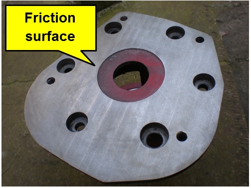
This photograph shows the friction face of the casting after machining – back to “as new” out of the factory. It needed about 60 thou removing but clearances are such that this was ok.
Given that so much had been pulled apart, it seemed like a good opportunity to have a look at the gearbox so its cover was removed.
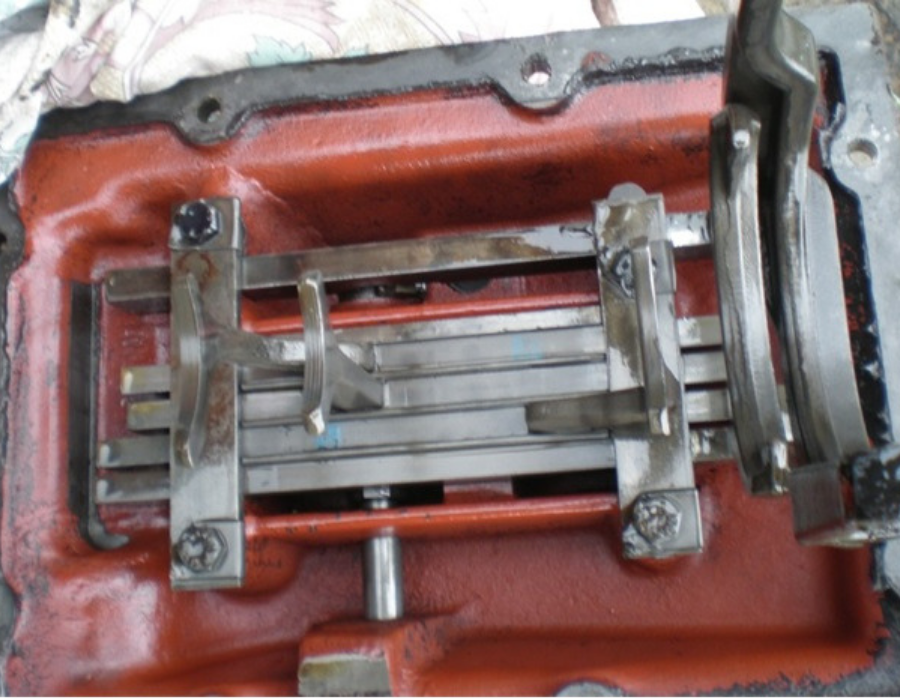
It can be helpful to select neutral and high ratio then photograph the position of the selectors as seen in this photograph of the underside of the cover.
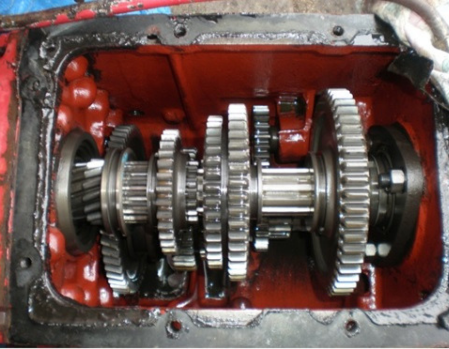
Another useful photograph is of the internals of the gearbox to record the position of the gears for when the cover is replaced – they all need to be aligned correctly with the selectors or things will not work as expected. Fortunately, all the gears and selectors seemed to be in very good condition.
Re-assembly is simply the reverse of the dismantling process!
Most of the re-assembly isn’t that difficult with care but there are a few points to be aware of:
1. The diff bearing oil seal is 2.43” outside diameter, 1.62” inside diameter and 0.5” thick. The seal on the right brake housing for the diff lock selection shaft is 1.5” outside diameter, 0.875” inside diameter and 0.375” thick. These are readily available online from bearing suppliers.
2. Assemble the right diff bearing housing onto the differential first, taking care not to damage the shims. The differential clutch is retained by a pin (item 1 in the previous exploded parts diagram) – this pin locates in a slot in the differential half-shaft and can be difficult to align. The simplest solution is to look through the differential from the left of the tractor to align the pin with the slot and clutch with the splines.
3. With the differential bearing housings replaced, the spring, O-ring retainer and retaining wire clip can be refitted. Again, the special tool makes life much easier. The O-ring retainer has an internal and external O-ring – standard BS115 (outer) and BS112 (inner) Nitrile O-rings are very slightly larger cross section than the original parts but are readily available and arguably better.
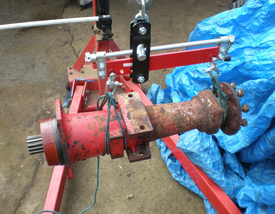
4. The right back axle is installed before the left. The crane and leveller makes alignment of the bull gear and axle half-shaft splines easier. Ensure that the correct shims are installed between the bull gear retaining bolt and the axle half-shaft and the correct torque used when finally tightening the bolt. Repeat for left rear axle.
5. Refit the PTO shaft ensuring that the PTO clutch is as shown in the earlier photograph and the PTO selector pin is engaged in the clutch’s groove.
6. Refit the PTO seal housing
7. Refit the hydraulics.
8. Refill transmission and hydraulic oil.
9. Reassemble the brakes.
10. Refit the wings, footplates and wheels.
11. Adjust the brakes
… and after all this, the brakes work as they did when the tractor left the factory.
ARTICLE CONTRIBUTED BY ANDREW CHAPMAN
© ANDREW CHAPMAN & ANGLO AGRIPARTS LTD
PART 1 - BRADFORD BUILT HARVESTER BRAKES >>
SHOP FOR EARLY BRAKES PARTS >>
SHOP FOR LATER BRAKES PARTS >>


Licence Terms
You are free to: Share, copy & redistribute the material in original format for any purpose as long as you follow the license terms below:
- Attribution – you must give appropriate credit and provide a link to the original article in a reasonable and visible manner
- You may not in any way suggest that the licensor endorses you or your use.
- No Derivatives – The material must be distributed in full, including disclaimer, you may not distribute or share modified material.
- No additional restrictions – You may not apply legal terms that legally restrict others from doing anything the licence permits.
- No warranties are given. The license may not give you all of the permissions necessary for you intended use. For example other rights such as publicity, privacy, or moral rights may limit how you use the material.
Anglo Agriparts nor any such reviewers or contributors of content provides any warranty or guarantee as to the accuracy of any information on this website and cannot accept liability for any errors or omissions. The information in this article are for general information purposes only. It does not constitute legal, technical and/or commercial advice and should not be relied upon as such. Specific advice should always be sought separately. Despite the authors best efforts the information provided in this article may not be accurate, up to date or applicable to the circumstances of any particular case. Anglo Agriparts nor the author of this article make no representations or warranties of any kind regarding the completeness or accuracy of the information contained herein and accepts no liability for loss or damage whatsoever and howsoever arising from reliance on it, regardless of whether such information originates from Anglo Agriparts, or our contributors. Anglo Agriparts has no control over the content on any other website accessed through this website and accepts no liability for any loss or damage whatsoever and howsoever arising from reliance upon the content of such websites. Neither Anglo Agriparts nor any reviewer or contributor of content on the website shall be liable to any person for any loss or damage which may arise from the use of the information contained in this article or on this website. These exclusions of liability will not apply to damages arising from death or personal injury caused by the negligence of Anglo Agriparts or any of its employees or agents or of a reviewer or contributor of content.


