
Drawing on his experience restoring and maintaining diesel engines Andrew Chapman's recent article focuses on diesel engine injectors.
Andrew is currently restoring International Harvesters ’61 B275, ’67 B434 - and has contributed to the International B Series Tractors Group and a number of instructional files to the International Harvester Club of Great Britain.
Diesel Injector Testing and Overhaul
WARNING Diesel injectors operate at very high pressures (2,000 psi upwards) and, if treated carelessly, can inject diesel into flesh or eyes with very serious consequences – wear gloves and safety glasses. Care should be taken to ensure that any jets are kept well away from anyone in the testing area.
Before blaming poor starting or running on injectors one should always check for the more common problems:
-
Are valve clearances ok?
-
Is the compression ok? Low compression or more than 10% difference between cylinders is abnormal.
-
Are the glowplugs working ok and free from carbon build-up?
-
Are there any starter motor/battery problems?
Introduction
The following information is primarily focused on the types of injectors typically found in diesel engines manufactured from about the 1950s onwards but excludes modern types with integrated electronics. The end results are not likely to be up to the standards of the professionals but should be adequate for our old tractors.
If one considers a typical tractor engine that has operated for about 5,000 hours at 1,500 rpm, each injector will have operated about 225,000,000 times. Just as water wears away rock over time, so diesel will wear the critical metal parts of the injector… and that is before one considers the long term effects of combustion.
Poor injectors can result in difficult starting and white smoke. Sometimes an engine will not start on all cylinders, only firing on some cylinders when it has started to heat up. Other possible side effects of injector problems include cylinder knock, engine overheating, loss of power, smoky black exhaust and increased fuel consumption.
Parts of a Typical Injector
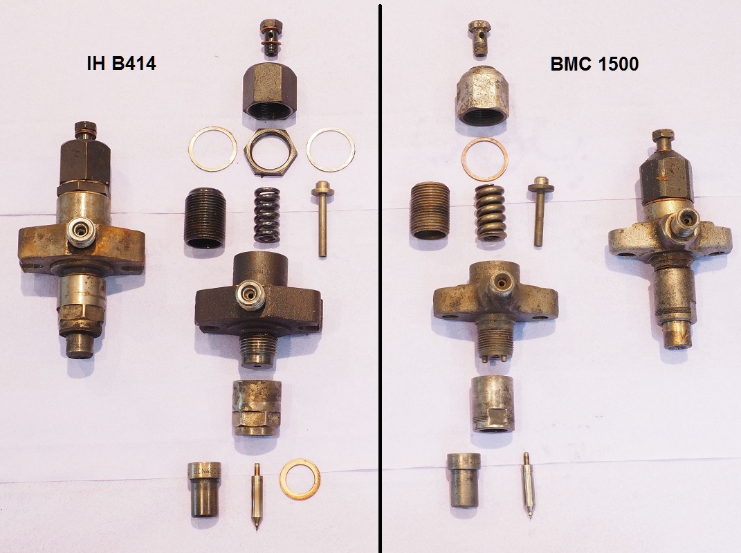
While there are lots of different injectors around, their principles of operation are similar. The following picture shows two different injectors from the 1960’s, one being from an International Harvester B414 (although the same parts fits all the Bradford built tractors) and the other from a BMC 1500 engine (fitted to the Leyland 154). Each injector is pictured complete and disassembled.
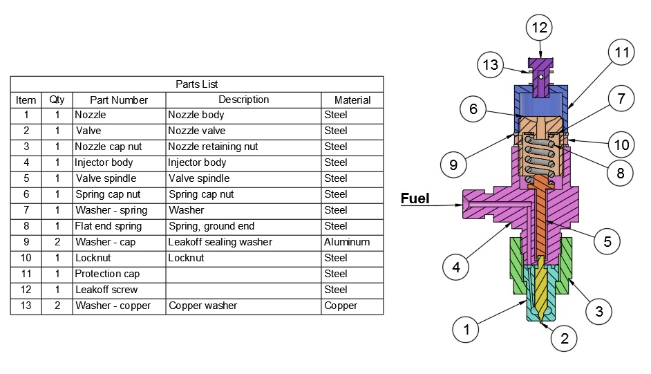
The following diagram shows a cross section through a CAV injector as fitted to the International Harvester BD144 and BD154 engines used in the Bradford built tractors. As can be seen from the previous photograph however there is little difference between other CAV injectors or even those from other manufacturers.
Nozzles
The nozzle and associated valve (items 1 & 2 in the previous diagram) are the primary wearing parts. They are generally readily available and quite easy to replace, but the injector should also be adjusted to ensure that it operates at the correct pressure.
The following pictures were taken after the nozzles and valves had spent at least an hour in an ultrasonic cleaner filled with carburettor cleaner. Before cleaning they were covered in heavy carbon deposits.
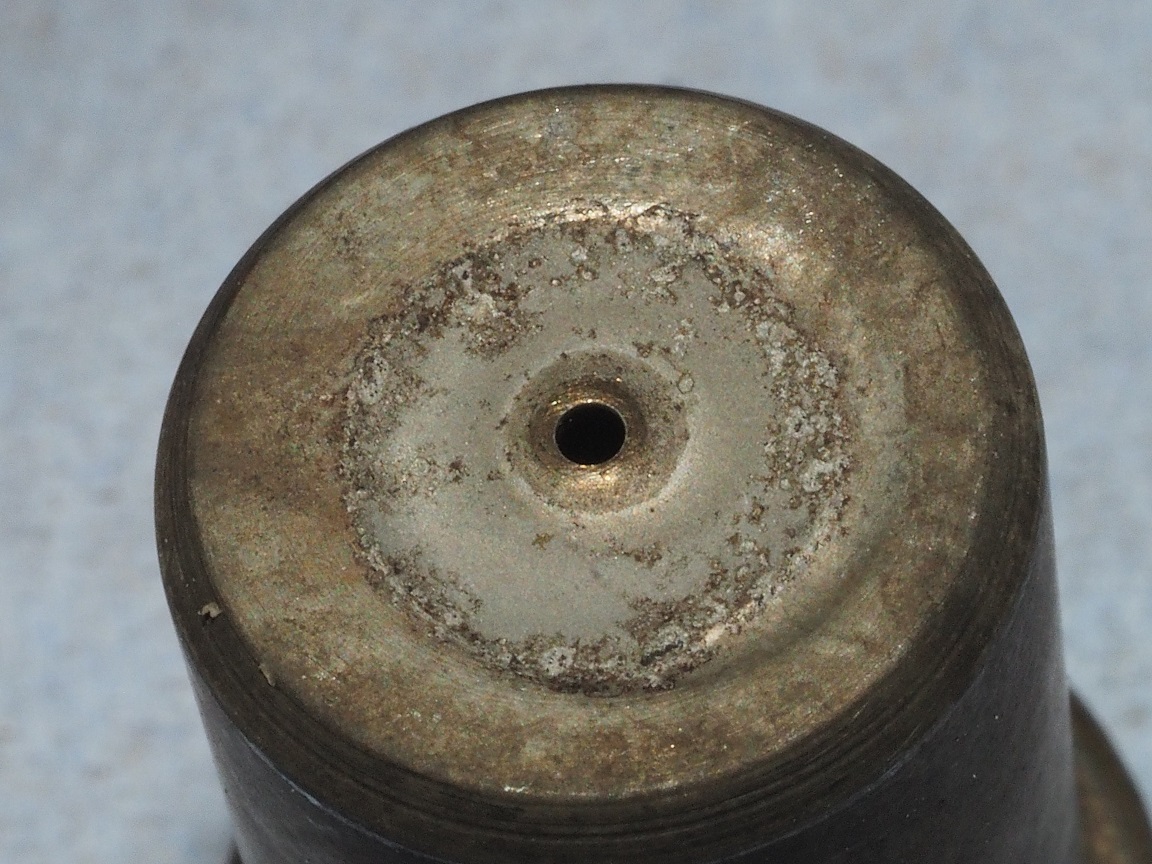
Nozzle from an International Harvester BD154 engine in a B414. This is in relatively good condition – at least from the outside.
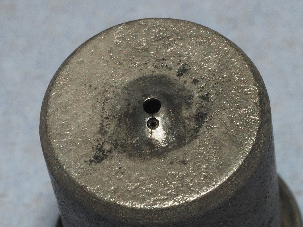
Nozzle from a BMC 1500 engine. Note the smaller pilot hole to squirt fuel onto glowplug and the radial crack through both holes.
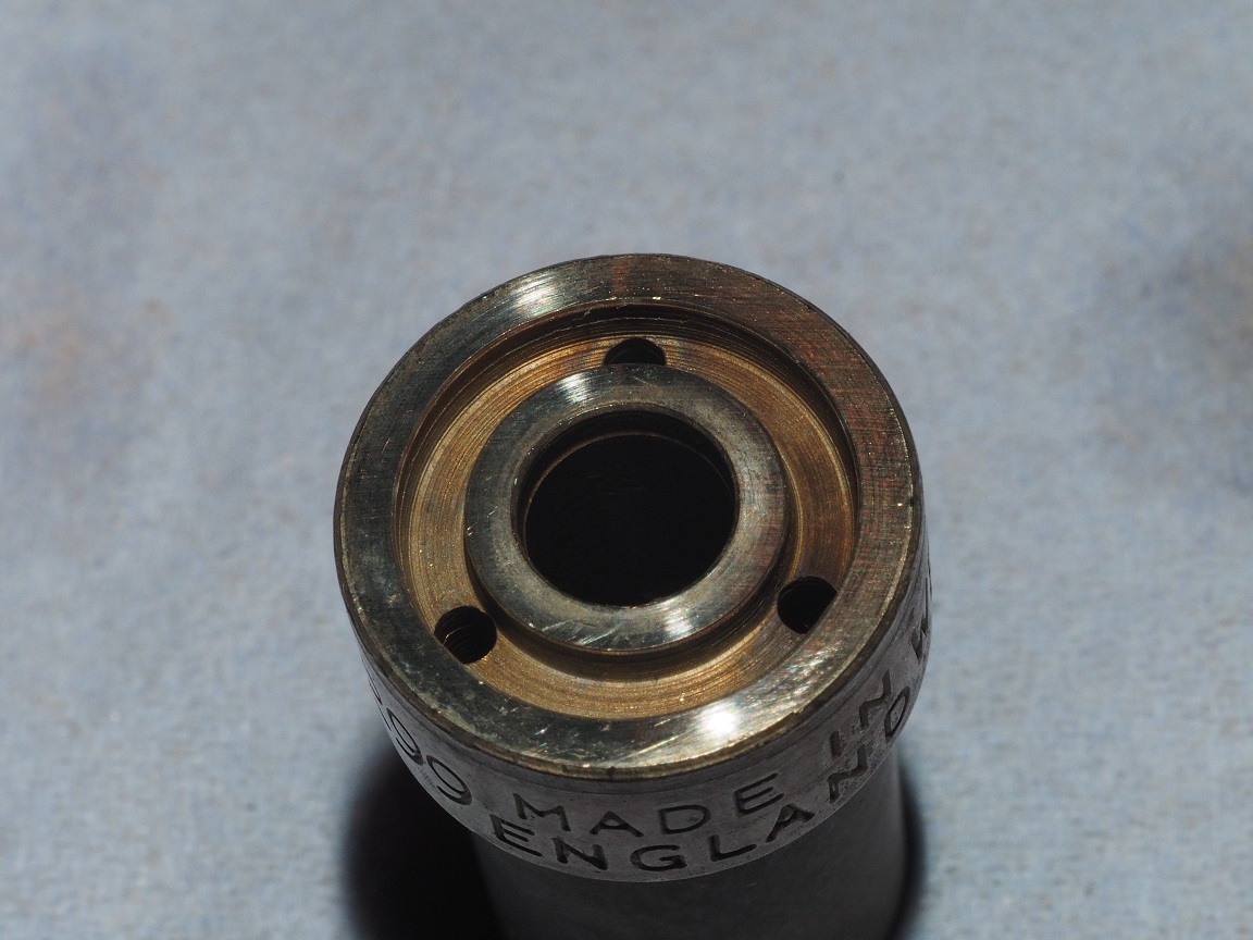
Nozzle from an International Harvester BD154 engine in a B414. This has three fuel feed holes in a recessed ring as this nozzle doesn’t need a specific orientation.
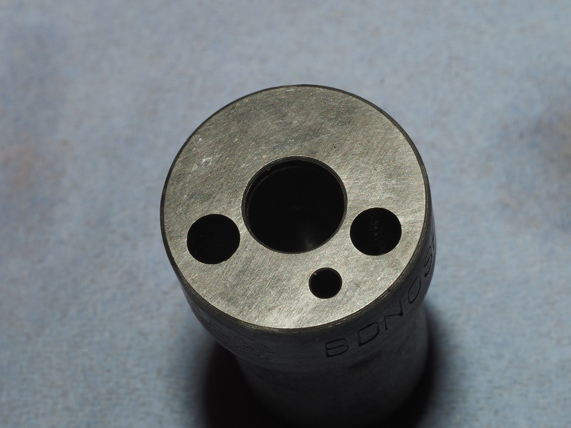
Nozzle from a BMC 1500 engine – other end. The smallest hole (bottom right) is the fuel feed, the other pair being for dowel pins in the injector body to ensure the pilot jet points in the correct direction.
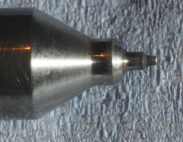
This valve, as can be seen when compared to those on the right, has worn badly with the end having a much smaller diameter and is tapered. When the injector was tested it squirted a solid jet of fuel – not atomised as it should have been. When rotated, the tip of the valve was also seen to be bent, a sign of mishandling of the injector outside the engine at some time.
These are a pair of old (top) and new valves from equivalent nozzles. There are minor differences in design including the new one showing a slight concave curve, possibly to generate a wider spray pattern. The top valve shows little wear.
Operation
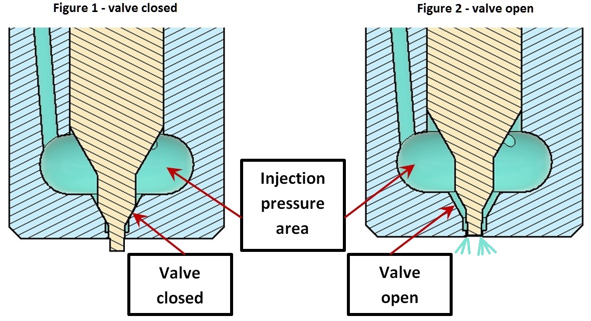
The injection pump feeds fuel into the injection pressure area in the above diagrams. The only “seal” between valve and body is a tight tolerance fit. A small amount of fuel leaks past the valve and lubricates it – this flow is the “leakdown” which is eventually returned to the fuel tank. More wear between valve and nozzle results in higher leakdown.
While the pressure is low the valve remains closed by the spring and valve spindle (items 8 & 5 in the previous sectional view.) The cross section area where the valve seats (pointed to by the “Valve closed” arrow) is much smaller than the valve’s main body area – the difference provides a lifting force which, at a pressure determined by the spring, eventually causes the valve to lift off its seat allowing fuel to be released. Once the valve starts to lift from its seat there is a rapid drop in pressure in this area leading to more valve lift. This rapid positive feedback causes the valve to snap open quickly… but only if it doesn’t stick or there is a poorly sealing seat.
The valve shown here is a pintle type which has an end which projects beyond the nozzle body when closed. This end is of smaller diameter than the higher length and, as it lifts into the nozzle hole when it opens, fuel passes between the pintle and hole. The shape of this end section accelerates the fuel (venturi effect) and lowers its pressure – working correctly it leads to a very fine atomised spray. A fine atomised spray will ignite much more easily than a jet of liquid and burn more uniformly, producing more power.
The valve stem moves in the nozzle body using fuel as a lubricant. A new nozzle/valve has very tight tolerances – there will always be a small amount of leakdown (necessary to stop the valve seizing) but when this increases then everything else also tends to have become worn.
When the nozzle, valve and injector pump are working correctly together, the valve should seal without dribbling then make a rapid transition from closed to open (again influenced by the valve shape) with a fine mist-like spray.
So, to get correct operation, the nozzle and valve must move smoothly, have its correct shape to atomise fuel, be free from carbon and other deposits. In a well operating engine these don’t tend to be too much of an issue but wear will occur over time and lead to a deterioration in jet atomisation and shape. Wear will also lead to an increase in leakdown.
Testing, Inspection and Adjustment
Professional injector test equipment can be very expensive but for an investment of less than £100 (at the time of writing) it is possible to be in a position to test and refurbish injectors for not much more than the cost of a single exchange unit. Rebuilding an injector probably will probably require a new nozzle, but these tend to cost 10 to 20% of the cost of an exchange injector.
One piece of information needed is the injector’s intended opening pressure. Hopefully this can be found from the workshop manual or other documentation but if not, taking the average from the removed injectors (before disassembly) is better than nothing.
Tools
The following are examples of the types of tools that may be helpful:
-
Jeweller’s loupe to allow visual inspection. These are available with x30 magnification via the internet for less than £3.
-
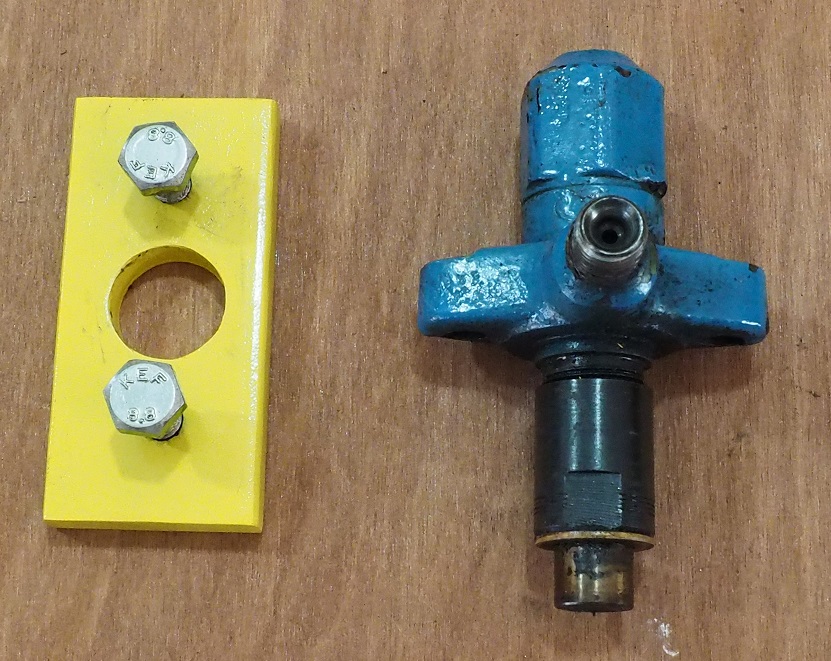
Injector holder (homemade). Some injectors can be held in the vice by their mounts without damage but sometimes a length of steel with 3 holes (injector body and two fixing bolts) may be needed to hold the injector while undoing or tightening parts.
-
Testing pump. This is the major cost item but several different types are available around the £90 mark.
-
Ultrasonic cleaner and carburettor cleaner. This isn’t absolutely necessary but once purchased they tend to get used for all sorts of other jobs. For injectors one could probably get away with a basic 2 litre type (£40) although a 3 litre heated type (£80) is probably of more general use.
On Engine Testing
These tests assume a rotary injection pump is used. If the engine has an inline pump then injector pump problems could give the same effect as a faulty injector.
If a test pump is available then that is much more informative, but this procedure will allow some testing without special equipment.
Assuming the engine will run:
- Disconnect the leakdown pipes and direct the injector leakdown into a clear plastic bottle per cylinder. Run for a few minutes and check how much fuel is in each bottle. If a bottle has nothing the valve may be stuck open. If there is much more than an egg cup full of fuel then the valve is leaking too much and would benefit from replacing. A quicker but messy alternative is just to run without the leakdown pipes and see how much fuel is discharged.
- With something to catch any fuel, try each injector in turn releasing the fuel pipe nut ½ a turn. If the engine note changes then the injector is at least doing something. If there is no change then the cylinder isn’t firing – if compression is ok then the injector is likely to be faulty.
- With the engine disabled from running (e.g. glowplugs out), remove injectors one at a time and reconnect to their fuel line with the nozzle into a clear plastic bottle. Take great care to keep well out of the spray and safety glasses are a good idea. Crank the engine and observe the spray through the bottle wall – it should be a uniform fine mist. Compare all cylinders – any injectors that look poor should be rebuilt.
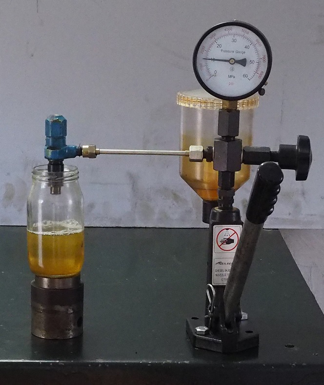
Test Pump
The low cost test pumps are easy to use but a little practice will be needed to get consistent results as they potentially can deliver much more fluid in a single stroke than the engine’s injector pump. As a consequence the valve lifts higher than normal in the nozzle and the resultant behaviour isn’t indicative of what happens in the engine.
Testing is done with an injector connected via a suitable adaptor to the pump. The adaptor pipe is normally strong enough to support the injector.
A clear container should be positioned under the injector and high enough to be above the nozzle output. Something like a bottle with a small neck is handy to stop injury from the jet/spray, but the aim is to be able to safely observe the nozzle output.
- Pump slowly to pressurise the system and bleed air while checking for and, if necessary, removing leaks. Let the injector discharge a few times to remove air.
- Pull the lever down slowly while watching the pressure gauge and note when the valve opens. Repeat several times – the opening pressure should be consistent.
- Increase the pressure slowly to just below the opening pressure. There should be no dripping from the valve tip.
- Operate the pump slightly quicker and observe the spray pattern – it should be a uniform fine mist without obvious jets (unless there is a pilot jet as on the BMC 1500) and there should be a noticeable “burp” sound as the valve rapidly opens. Knowing what a good injector sounds like takes a little practice and a good injector!
- Repeat for the other injectors – all should operate at the same pressure and with a uniform mist spray.
Any injectors that are not perfect will need stripping, cleaning and retesting.
Strip-down, Cleaning and Inspection
If the injector is a pintle type (part of the valve extends beyond the end of the nozzle) care should be taken to ensure that this is not damaged by careless handling.
When finally dismantled, care should also be taken when handling the valve as this and the way it fits and moves in the nozzle is critical to reliable operation. The fit between these two parts is to very fine tolerances so no grit or other debris should be allowed to come into contact with their sliding and sealing surfaces. This care should also extend to handling the valve as even the acid from human hands can cause damage – lightweight medical type gloves are therefore recommended both to protect the valve from damage and your hands from the fuel.
It can be helpful to initially clean the outside of the injector before initial disassembly – degreaser, wire brush or ultrasonic bath with carburettor cleaner… or even an old toothbrush.
Strip-down
The initial strip-down requires the injector to be firmly held in a vice. Depending on the design of the injector this may need some simple support to be made as shown in this photograph to fit the BMC 1500 injectors. The IH B414 injectors, having flat sides can simply be held in the vice.
The protection cap should be removed first, followed by the locknut if one is fitted. Some injectors have no locknut – the same engine may even have different styles of injector depending on its service history. These nuts can sometimes be very tight so a 6-sided socket (to get maximum purchase and minimise damage to the nut) and long bar may be needed to free them.
NOTE: This injector had been assembled with PTFE tape on the thread. The seal is a metal to metal one where the olive on the pipe fits into the recess in the injector and no tape is needed or should be used. 2 of the 4 injectors on this particular engine had tape on the threads.
With the protection cap removed, unscrew the spring cap nut. Inside this nut there is normally a plain washer between it and the spring – the washer may be held inside the nut or drop out while handling.
The spring can be lifted out followed by the valve spindle.
The injector can now be inverted in the vice and the nozzle nut removed. This nut sometimes has a hexagonal head (again a 6-sided socket is a good idea) while others have two flats part way along the nut. The later type of nut needs a well-fitting open ended spanner to avoid damage as, with the protection cap, sometimes they are very tight.
With the nozzle nut off, the nozzle and valve come away together although the nozzle may be stuck in the nut due to carbon build-up. If they are stuck then placing them between two pieces of softwood (remove the valve first to avoid damage) and careful use of a hammer should free them – to avoid damage, do not use a hammer directly on the metal.
The valve and nozzle is a matched pair and should not be mixed with ones from other injectors.
Cleaning
External cleaning is primarily for cosmetic purposes, but any parts and surfaces that will come in contact with, or to seal, fuel must be scrupulously clean. If they are not to be re-assembled immediately it can be sensible to store them for protection in fuel or very light oil (e.g. WD40.)
Unless it is known that the nozzles will be replaced, the nozzle and valve could be cleaned in an ultrasonic tank with carburettor cleaner. They should never be re-assembled dry or with any water on them as they are likely to jam. They should be assembled with a film of light oil or fuel.
Inspection
Inspection of most parts consists of simply checking that they have no obvious damage and are clear of rust (fuel areas and sealing surfaces) or other contamination.
The end of the nozzle should be inspected with a jeweller’s loupe – if damaged it will need to be replaced.
The end of the valve (pintle) should receive special attention as wear and deposits will significantly affect performance. Again, if there are signs of wear then the nozzle should be replaced.
Lubricate the valve with fuel or very light oil and while rotating the valve, slide it into the nozzle. The valve should slide smoothly without any binding. If there is any sticking the stem of the valve can be polished with paper towel soaked in fuel or oil… but nothing more abrasive, as this will ruin the valve.
Rebuild and Adjustment
Rebuilding is the reverse of disassembly but cleanliness is critically important as a single piece of grit or fibre could ruin the nozzle/valve performance.
-
Insert lubricated valve into nozzle as previously mentioned.
-
Fit nozzle to injector body and fully tighten the nozzle nut. If the nozzle has locating dowels as in the BMC 1500 injector pictured earlier, take care that they are correctly aligned before tightening the nut
-
Invert the injector body in the vice and insert the valve spindle and spring.
-
Fit the spring cap nut, along with the top washer if one was fitted. This nut should be hand-tight only at this stage.
The injector can now be mounted on the test pump with a clear container to catch the fuel.
Operate the pump slowly to eject all air then watch the pressure gauge to determine the injector’s opening point. The spring cap nut can be adjusted to bring the opening point to that specified for the injector. Some caps have a slot so they can be turned with a large screwdriver or coin but others are simply turned by hand.
Once the opening point has been set, dry the end of the nozzle and then raise the pressure to just under the desired opening point. The valve shouldn’t leak.
Operate the pump handle more quickly to get the injector to “burp”… assuming everything is working correctly. This takes a little practice as the intention is to eject a small amount of fuel only as would be the case in normal operation – delivering too much will lift the valve too high and the flow will no longer be shaped by the pintle, just the nozzle hole.
If the nozzle has a secondary jet as on the BMC 1500, this should produce a quite concentrated jet of fuel. The main hole however should produce a fine and uniform spray.
This process sounds quite complex and it is difficult to describe the sounds and spray patterns easily but, having looked at a set of injectors, it should become quickly obvious if they are working correctly or not, especially if a one with new nozzle is at hand as an example.
Assuming everything is now working correctly the locknut and washer (assuming fitted) can be tightened, and then the protection cap and washer fitted. Re-test to ensure that the opening pressure hasn’t moved.
The injector is now ready for replacement in the engine.
Special thanks to Robin Dare for the photographs.
ARTICLE CONTRIBUTED BY ANDREW CHAPMAN
© ANDREW CHAPMAN & ANGLO AGRIPARTS LTD


Licence Terms
You are free to: Share, copy & redistribute the material in original format for any purpose as long as you follow the license terms below:
- Attribution – you must give appropriate credit and provide a link to the original article in a reasonable and visible manner
- You may not in any way suggest that the licensor endorses you or your use.
- No Derivatives – The material must be distributed in full, including disclaimer, you may not distribute or share modified material.
- No additional restrictions – You may not apply legal terms that legally restrict others from doing anything the licence permits.
- No warranties are given. The license may not give you all of the permissions necessary for you intended use. For example other rights such as publicity, privacy, or moral rights may limit how you use the material.
Disclaimer


