
The last in his series on brakes Andrew Chapman provides a study on tractor handbrakes and brake locking on.
Early Handbrakes
Over time and even with correctly adjusted foot brakes, the early handbrakes get to the point where they will no longer lock the brakes on.
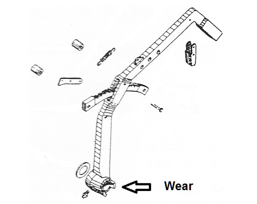
The cause for this is wear at the bottom of the handbrake lever where it engages with the footbrake pedal as shown in this diagram.
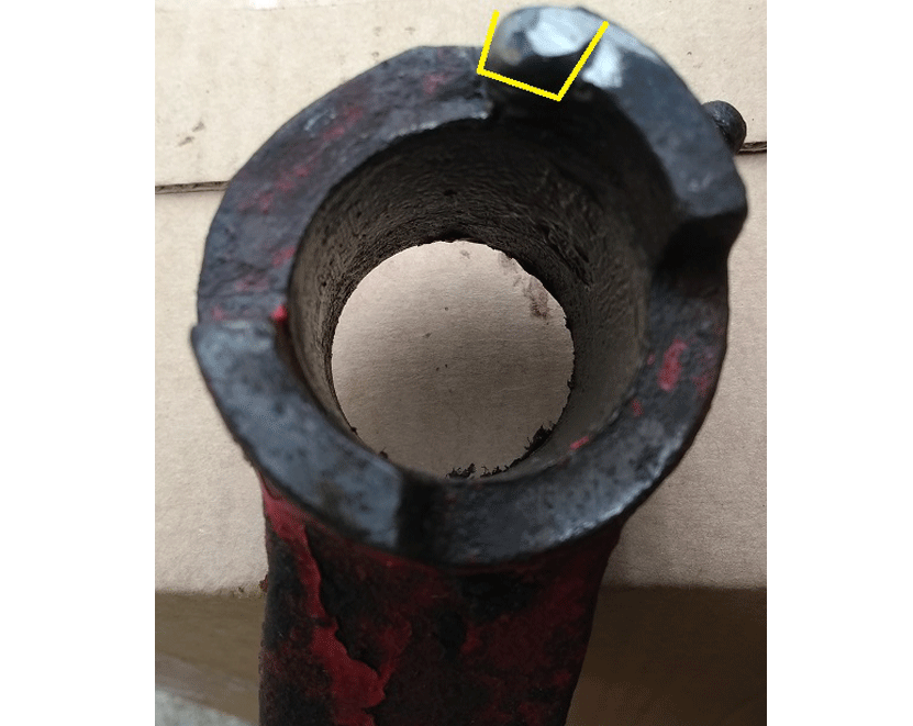
The solution fortunately is relatively simple as shown in this photograph. The projection at the top of the photograph locates in a mating slot in the footbrake pedal but on examination the area highlighted in yellow had worn away.
Simply welding and a quick reshape with the angle grinder returned the handbrake to the middle of its travel with the brake locked firmly on.
Later Handbrakes
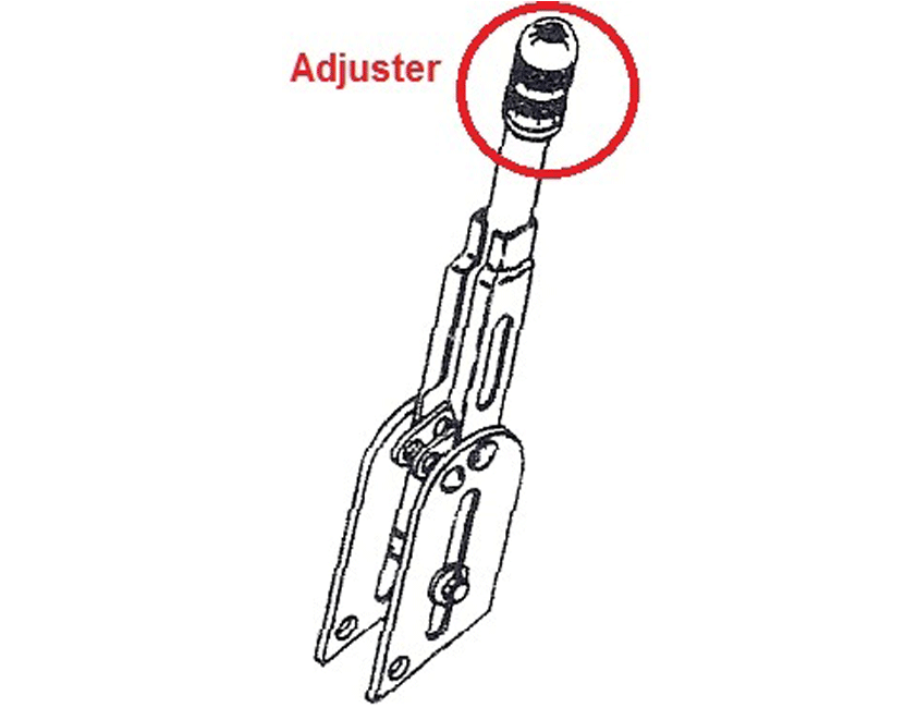
Later tractors with the larger brakes also had a different handbrake. This handbrake includes an adjuster which, looking at how it is painted on many of the restored tractors, possibly many owners don’t know about.
This picture shows the position of the handbrake adjuster which is explained in more detail in the following cutaway section through the handbrake handle
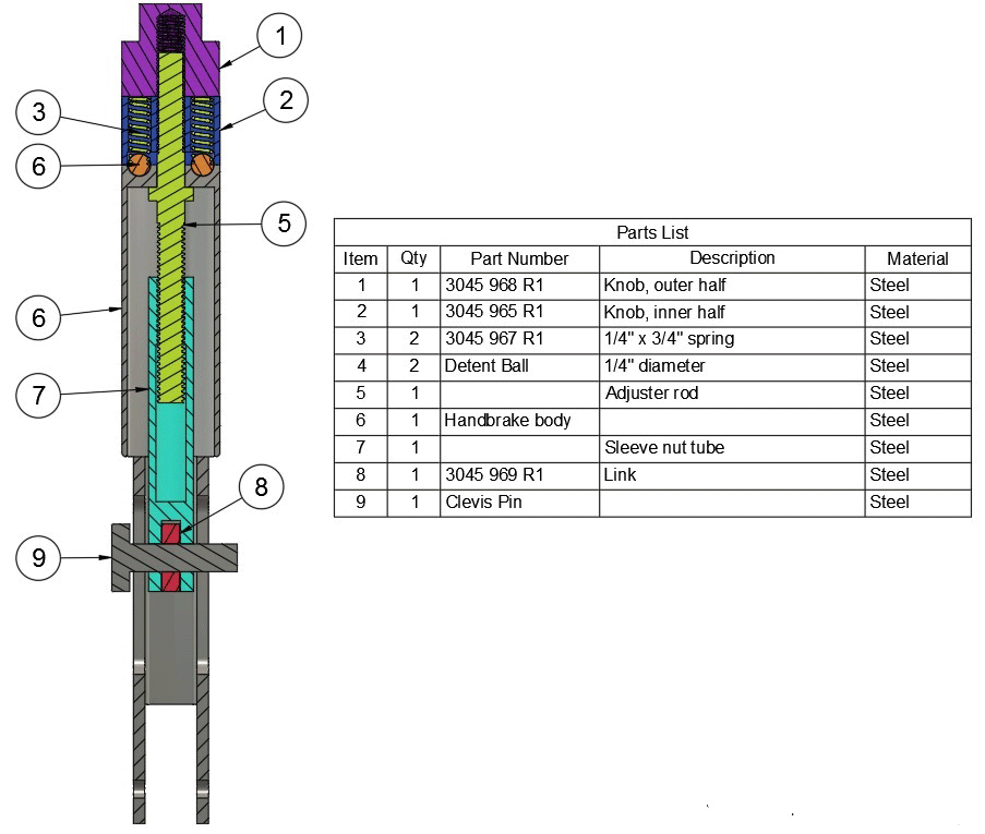
The top has two nuts. Item 1 is a lock nut to hold two springs (item 3) and detent ball bearings (item 6) in the second nut (item2.) Items 1 and 2 lock together to clamp to the adjuster rod (item 5) which screws in and out of the sleeve nut (item 7) taking up the brake slack when pulling on the link arm (item 8.)
In the top of the handbrake body (item 8) are four detent holes into which the detent balls click.
So, when operating correctly, items 1 and 2 are turned by hand with the handbrake off and four clicks per revolution will be felt. Turn clockwise to tighten up the handbrake locked position, anticlockwise to slacken.
Replacement levers are available from some suppliers but were not necessary for the two tractors recently repaired. The first simply required freeing off, lubricating and adjusting while the second needed items 6 and 7 made on the lathe from old wing retaining bolts from the same machine, keeping it original.
Brakes Locking On
A recurrent problem on the Bradford built International tractors, and others of the period, is that the brakes can lock on when they are operated. Sometimes they will release if the tractor direction is reversed but in really bad cases the adjuster needs to be unwound too before they will free.
Knowing about the problem and finding the cause however are two different things. Several possible causes have been voiced in the past from people who have worked on these brakes, typically including copper grease on the actuator ball bearings and smoothing the faces of the brake housings (also coated with copper grease), but generally the problem remains.
The following is therefore the author’s explanation of what happens, why and then how to fix the problem. The tractor used to prove this solution was a ’61 B275.
How the Brakes Should Work
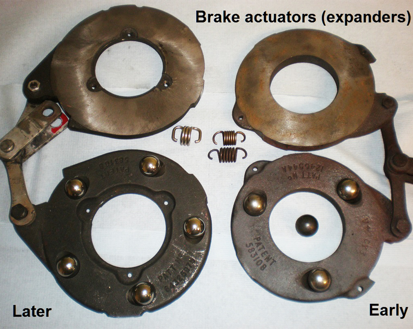
The heart of the brakes is the actuator assembly. The smaller early brakes used 3 ball bearings between the two outer halves held together with 2 springs while the later and larger units used 5 ball bearings and 3 springs. When the brake pedal is pressed the linkage causes the two halves to rotate slightly against each other with the ball bearings rolling up the teardrop shaped holes and forcing the plates apart.
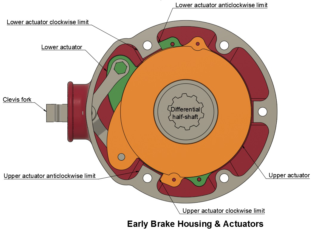
The diagram shows the early brakes which are similar to the larger later ones and those fitted to tractors from several manufacturers in the ‘50s and ‘60s. It also shows the actuator in the maximum position possible (brakes fully on) which would only ever be reached with very worn brake disks. The lower actuator is fully anticlockwise while the upper is fully clockwise at the same time, leading to maximum expansion of the actuator.
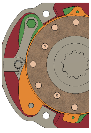
This second diagram shows the actuator in the minimum (brakes off) position… and includes a brake disk to complete the picture.
The actuators are located by the shape of the brake housing and can only move through a relatively small angle. When the brakes are applied the top actuator (orange) will move slightly clockwise relative to the lower actuator (green.)
Rotationally, exactly where the pair align will depend on the direction of the road wheels and the friction on the two outer faces of the actuators. This can change dynamically while braking and can result in a “clunk” if they suddenly rotate a few degrees and come up against one of the limits shown in the first diagram.
Why The Brakes Lock On
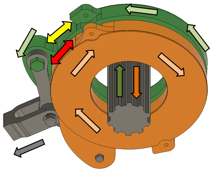
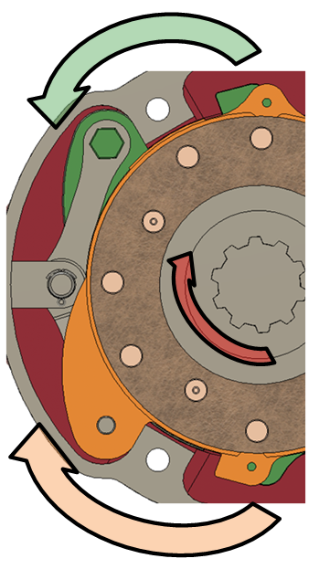
In this diagram the coloured arrows show how the two main parts of the actuator (the green and orange disks) move when the brake pedal is pressed. The brake pedal pulls the linkage (grey) and the two actuator halves rotate towards each other (roughly around the splined shaft axis as shown by the pale green and orange arrows) but are also pushed apart (along the splined shaft axis as shown by the darker green and orange arrows) by the ball bearing in the teardrop shaped holes.
The brake housing allows the actuator halves some rotational movement (possibly about 10 degrees) where the casting locates in the actuator area shown by the yellow arrow – there is a similar boss acting on the other half.
The face of the actuator with the red arrow also locates on the front of the boss – this is what the brake pedal actually pulls against.
This diagram shows the situation when the brakes are first applied with the friction disks rotating in the direction shown by the red arrow (clockwise.) Pedal pressure causes the actuator initially to be roughly aligned centrally and then gradually forces the green half to move anticlockwise and the orange clockwise.
As the two halves move apart the friction between actuator and brake disk increases. For one side of the actuator this is in opposition to the brake disk (green here) while the other side supplements the brake pedal force. In a perfect installation these forces balance and the actuator doesn’t turn one way or the other. In real (worn) brakes there is often an imbalance and the actuator eventually turns one way or the other until stopped by the lugs on the brake housing… sometimes accompanied by a noticeable “clunk”!
But what happens when the linkage becomes worn? There are several joints in this linkage – clevis to arms, straight arm to one side of the actuator and forked arm to the other. When new, these joints have minimal clearance but if there is a significant amount of play there comes a point where brake disk friction causes one side of the actuator to rotate and take up the slack. That actuator half must already have a relatively high braking force but, as it rotates still further this increases the braking even more. If there is enough movement then the forward motion actually forces more and more braking until all the play has been taken up (and movement is stopped by forces against the other actuator) or the brakes lock solid. This could even reach the point where the vehicle has to be driven in the reverse direction to free the brakes, and with the heat generated they may not even free then.
Fixing the Problem
The easy fix is to replace the whole actuator. Anglo Agriparts sell the actuator for the larger Bradford built tractor brakes (A62414) and the friction disk (A40060) while other suppliers have the springs if they have failed. The ball bearings are 7/8” diameter for both small and large brakes, again relatively easy to source.
Similar expanders are also available for other tractors that use this type of brake but unfortunately they are not currently available for the earlier Bradford brakes, so a different solution was adopted for the tractor under investigation.
The approach taken was to go through each joint in the linkage in turn finding ways to remove all play. Putting some numbers to the problem, one arm had about 2mm of play at the actuator while the other had about 1.5mm with a further 1.0 to 1.5mm at the clevis joint. With a cumulative slack of over 4mm there could be a significant unwanted rotation of the actuator.
Expander Bolts
The original bolts have a hardened shoulder on which the arms pivot. The bolts were grooved so new bolts were needed, but not available off the shelf. The solution adopted was to use a bolt that would fit the expander hole and make a sleeve out of 10mm diameter stainless steel to replace the shoulder on the original bolt. The sleeve was made a press fit onto the bolt and, when finally assembled with the arm, the bolt was riveted over to stop it coming loose in use.
Clevis Pin
The original clevis pin was 7/16” hardened but, as this size wasn’t readily available, a piece of 12mm stainless was used as a replacement. This was cross drilled at each end to take split pins – easy to make and keeping a high tolerance outer diameter and finish.
Arms and Clevis
Some of the holes in the arms and clevis were so badly worn that the holes had to be filled with weld then re-drilled. All holes were then reamed to size with the clevis end parts being reamed together to ensure good alignment. The fit here shouldn’t be too tight as this could also cause the brake to lock on. Aim for a fit without any sign of stiffness.
Residual clunk
Having rebuilt the problem brakes as described above they were reassembled on the tractor without any copper grease. Some people like to grease the ball bearings although that may collect dust and make matters worse. The other area that may benefit from grease is the faces of the brake housing where the expander rides against, but it was decided to keep everything dry so the only difference to the faulty brakes would be the removal of linkage play.
As with any reassembled brakes there was the need to road test, adjusting brake balance and pedal height. Before the rework the brake pedals had to be almost at the footplate before biting – if not the brakes (especially offside) would lock on.
Following rework, the brakes would bring the tractor to a halt against full engine power in top gear, and equally important, without any sign of locking on.
One initially concerning issue however was there was, at a specific high braking pressure, a pronounced loud “clonk”. This sound in the past has been associated with the brakes locking on but, as the brakes didn’t lock, is further confirmation that the actuators shifted position as described in the early explanation.
So, a positive resolution to a recurrent problem that plagues these tractors.
ARTICLE CONTRIBUTED BY ANDREW CHAPMAN
© ANDREW CHAPMAN & ANGLO AGRIPARTS LTD
PART 1 - International Harvester Bradford Built Tractor Brakes >>
PART 2 - Bradford Built International Harvester Major Brake Overhaul >>


Licence Terms
You are free to: Share, copy & redistribute the material in original format for any purpose as long as you follow the license terms below:
- Attribution – you must give appropriate credit and provide a link to the original article in a reasonable and visible manner
- You may not in any way suggest that the licensor endorses you or your use.
- No Derivatives – The material must be distributed in full, including disclaimer, you may not distribute or share modified material.
- No additional restrictions – You may not apply legal terms that legally restrict others from doing anything the licence permits.
- No warranties are given. The license may not give you all of the permissions necessary for you intended use. For example other rights such as publicity, privacy, or moral rights may limit how you use the material.
Disclaimer


